Jamo MPA-101 Stuck in Protection? Power Supply Repair
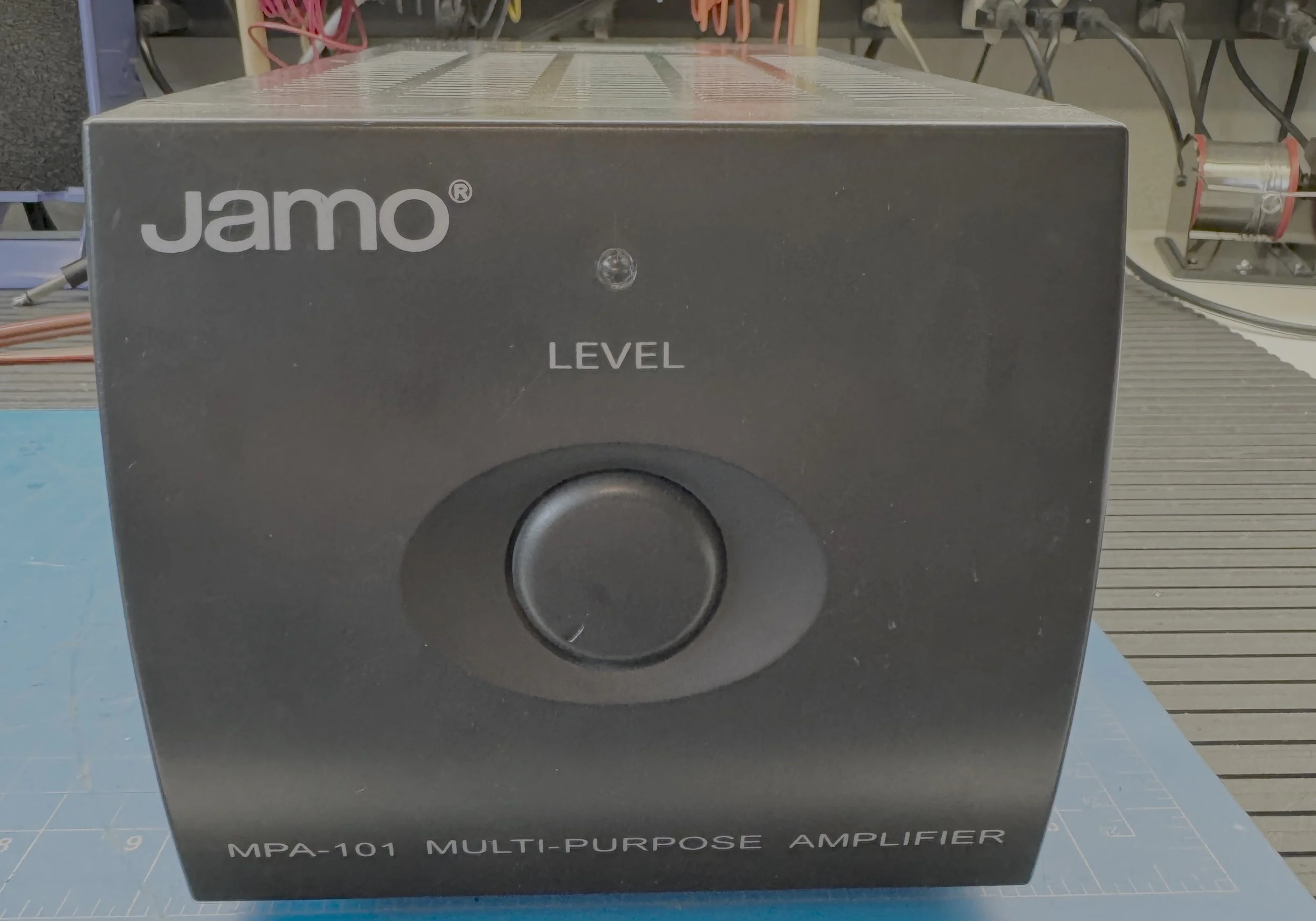
This Jamo MPA-101 powered on but remained in protection. The speaker relays did not click, and the cooling fan moved only momentarily at switch-on. Testing confirmed that the transformer, rectifier and main DC supply were operating, directing the investigation toward the auxiliary power supply and protection circuitry.
The eventual repair required ten electrolytic capacitors and four heat-stressed power resistors on the power-supply board.
Overview
This is a cheap ($150-$200) amplifier that is now discontinued that had failed and I was gifted by a customer for me to mess with. Before you race to buy one used on eBay or similar please read this.
Fault Condition: Would not power up, speaker relays did not click, and the fan seems to move for a brief second.
Initial Testing showed that the AC power was getting into the amp and the transformer and initial DC supply was all working.
Protection Circuit
This amp has a built in protection circuit that is designed to prevent damage to both the loudspeakers and the amplifier. It performs several functions simultaneously:
Delays connecting the speakers at power-up until the amplifier has stabilized.
Disconnects the speakers if excessive DC appears at either output.
Detects abnormal power supply conditions.
Prevents relay chatter during power-down.
The relay is the final output of the protection circuit and it is not the protection circuit itself.
This amp has two independent amplifiers, one for each channel, and a dual circuit power supply that powers each of them. The amps are bolted to a HUGE heatsink with a fan that cools the heatsink during use.
Note: The fan does not run continuously, turning on and off as needed.
Power-on delay
The delay is intentional. Without it, the loudspeakers would hear the charging transients of the amplifier as a loud "thump." A capacitor in the protection circuit creates a delay of typically 2–5 seconds before the relay is energized.
A healthy MPA-101 behaves like this:
Power ON
LED illuminates
2–4 second pause
Click
Music
DC fault detection
This is arguably the most important function. The protection circuit continuously monitors the outputs of both power amplifier channels.
In normal operation you will see Left output ≈ 0 mV DC, Right output ≈ 0 mV DC. If an output transistor fails, you may suddenly have +45v or -45v on a speaker terminal. Without protection, that DC would flow continuously through the loudspeaker voice coil, usually destroying it in seconds. If the protection circuit detects more than roughly 0.5–1 V DC (the exact threshold depends on component tolerances), it immediately de-energizes the relay.
Supply monitoring
The MPA-101 also monitors its internal power supplies. The relay is only allowed to close if the low-voltage control circuitry is operating correctly.
Typical problems include:
Missing supply rail
Regulator failure
Open dropping resistor
Excessive ripple from dried electrolytic capacitors
This is one reason a failed power supply often results in no relay click, even when the power amplifier itself is undamaged.
The relay driver
The relay coil is not driven directly by the timing capacitor. The capacitor controls one or more small transistors that act as a switch for the relay coil.
Why C39 is notorious!!
One component that appears repeatedly in MPA-101 repair reports is C39, a 220 µF electrolytic capacitor in the protection/timing section. As electrolytics age, they don't just lose capacitance, they can develop leakage current.
Instead of behaving like an open circuit after charging, a leaky capacitor behaves as though a resistor has been connected across it. The result is that the voltage on the timing node never rises high enough to turn on the relay driver transistor.
The amplifier therefore behaves as though a fault is permanently present:
Power LED on
Main rails present
No relay click
No audio
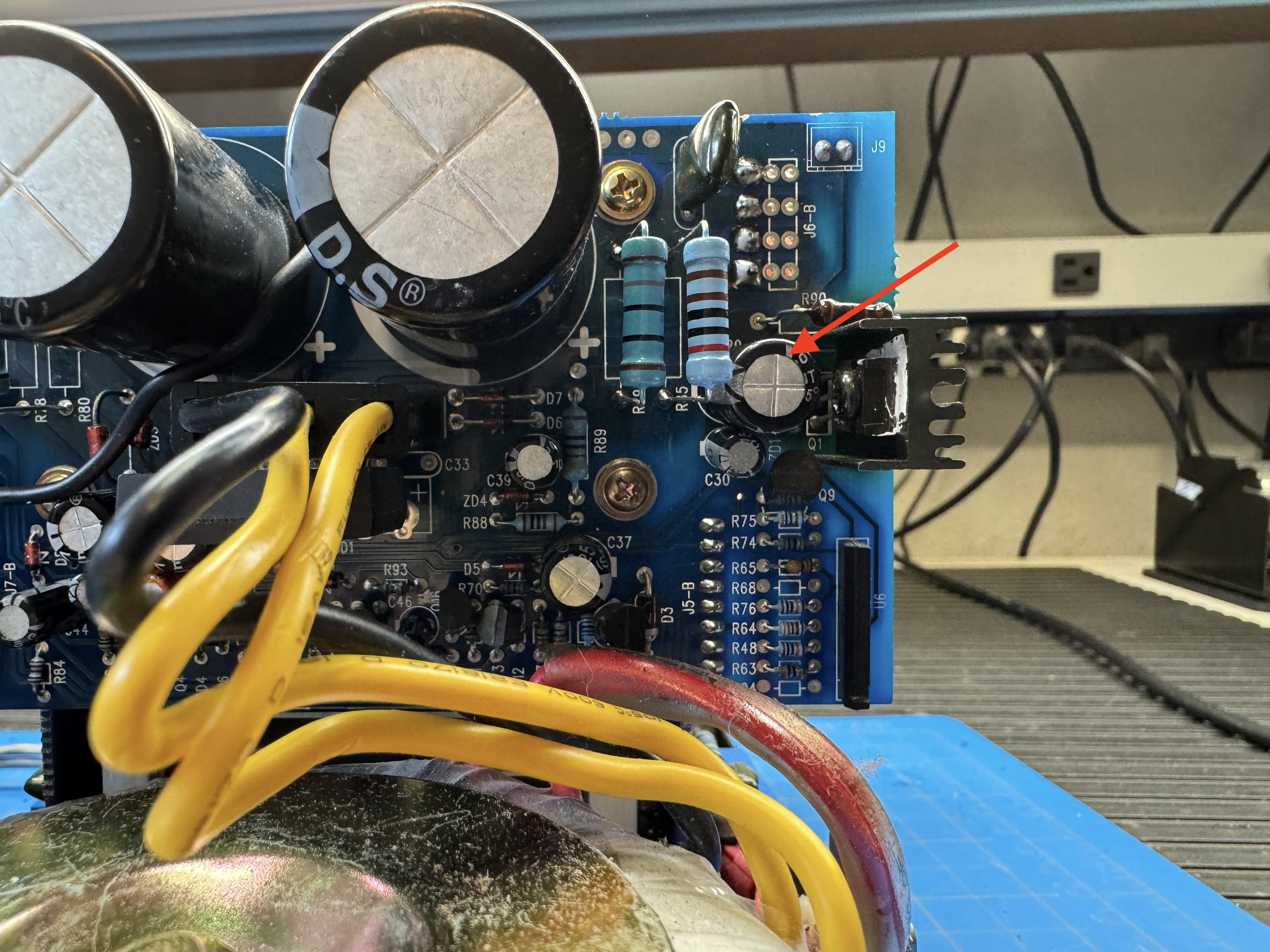
Replacing C39 has restored many otherwise healthy MPA-101 amplifiers. See the photo below. But read on!
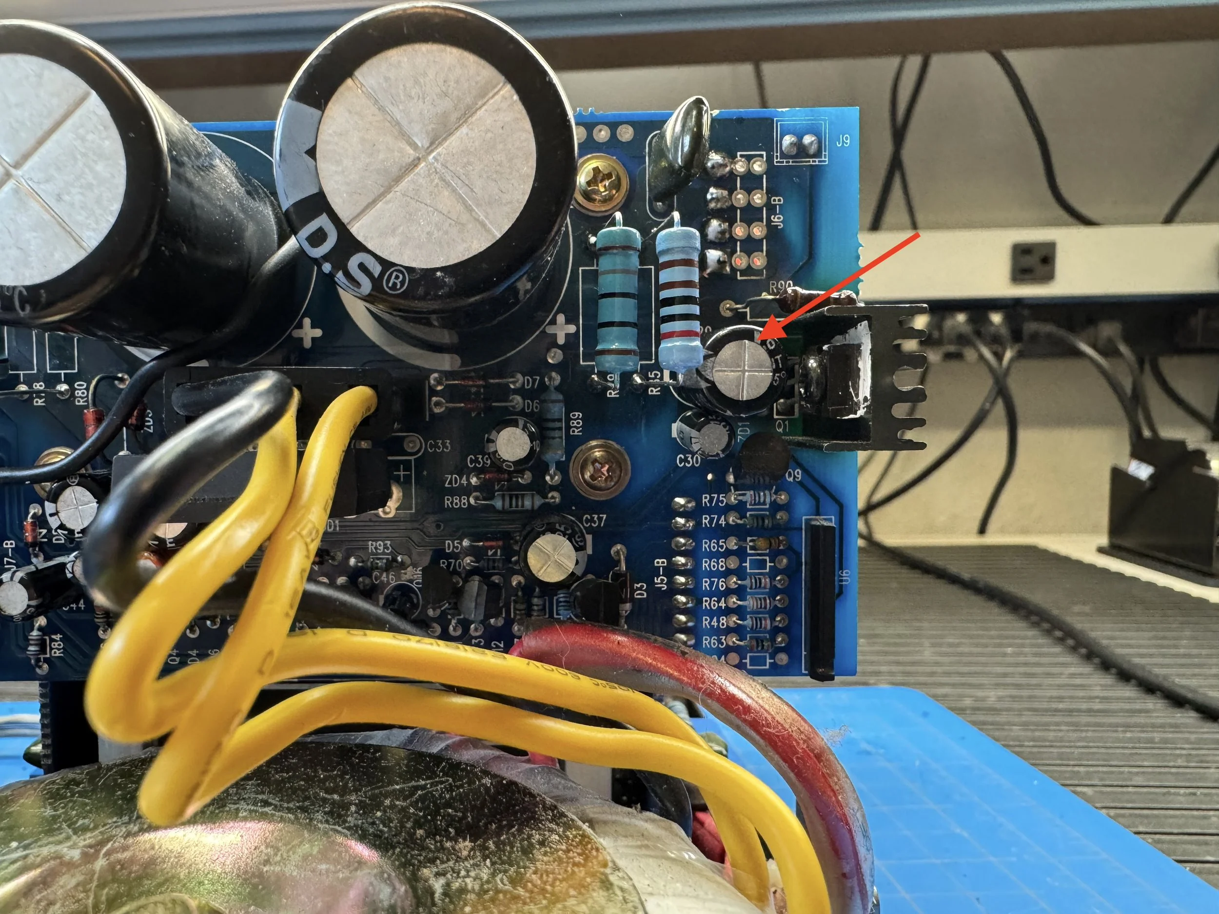
Follow the red arrow to C39. It’s positioned close to a regulator that runs warm. Prolonged exposure to this heat may contribute to accelerated capacitor ageing.
Common failure points in the protection circuit
Based on documented repairs and the circuit topology, the most common faults are:
Leaky C39 (220 µF) — prevents the timing voltage from reaching the relay threshold.
Open or drifted high-power resistors supplying the low-voltage/protection circuitry (notably R78 and R85).
Dried electrolytic capacitors in the low-voltage supply, causing unstable or collapsing control voltages.
Failed relay driver transistor, preventing current from reaching the relay coil.
Cracked solder joints, particularly around hot-running resistors, regulators, and the relay itself.
Relay contact wear, which causes intermittent or missing audio but does not prevent the relay from clicking.
I neglected to take before photos, so all the photos are after photos.
Caution
A missing relay click does not necessarily mean the protection circuit itself has failed. Before replacing components in the protection or auxiliary power supply, measure the DC voltage at both amplifier outputs on the amplifier side of the relay contacts.
If significant positive or negative DC is present, the protection circuit may be operating correctly and preventing that voltage from reaching the loudspeakers. In that case, the fault is more likely to be in one of the power-amplifier channels such as a failed output transistor.
Only proceed to investigate the relay timing and auxiliary supply once both channel outputs have been confirmed to be close to 0 V DC.
Overheated Resistors
Four power resistors in the auxiliary supply deserve particular inspection: R79 and R80 are 180 Ω, while R78 and R85 are 2.0 kΩ. All four are rated at 2 W and showed the effects of prolonged heat exposure. The resistor bodies showed substantial heat aging, although the resistors still measured close to their marked values.
They are 2W varieties. Some techs suggest using 5W resistors, but they are way too big. You could use 3W but I only had 2W. Now, if this was a customer’s amplifier I would have ordered some, but this is destined to be a bench amp for testing other gear so will only light use for the rest of its life.
Punchline: I had to replace 10 capacitors, and the 4 resistors.
Although all four resistors measured within tolerance when cold, they had experienced many years of elevated temperature. Because the power-supply board was already removed and the parts were inexpensive, I replaced them regardless.
Removing the power supply board is a real pain, and unless you have a professional desoldering station you risk burns, frustration, and damage to the PCB tracks and pads. Even with my pro tool it took a frustrating amount of time as you need to attack both sides of the power supply board, and on both sides of the board as it is soldered on both side. Both sides use a standard push on edge connector and then a soldered multi-pin through hole soldered edge connector, for no real reason in my view.
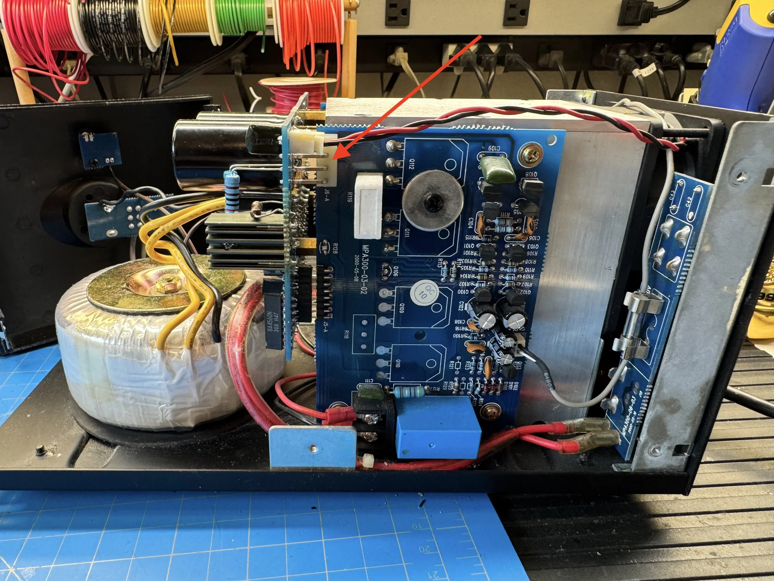
One of the edge connectors. Disconnect the lead above before spending 30 mins desoldering it.
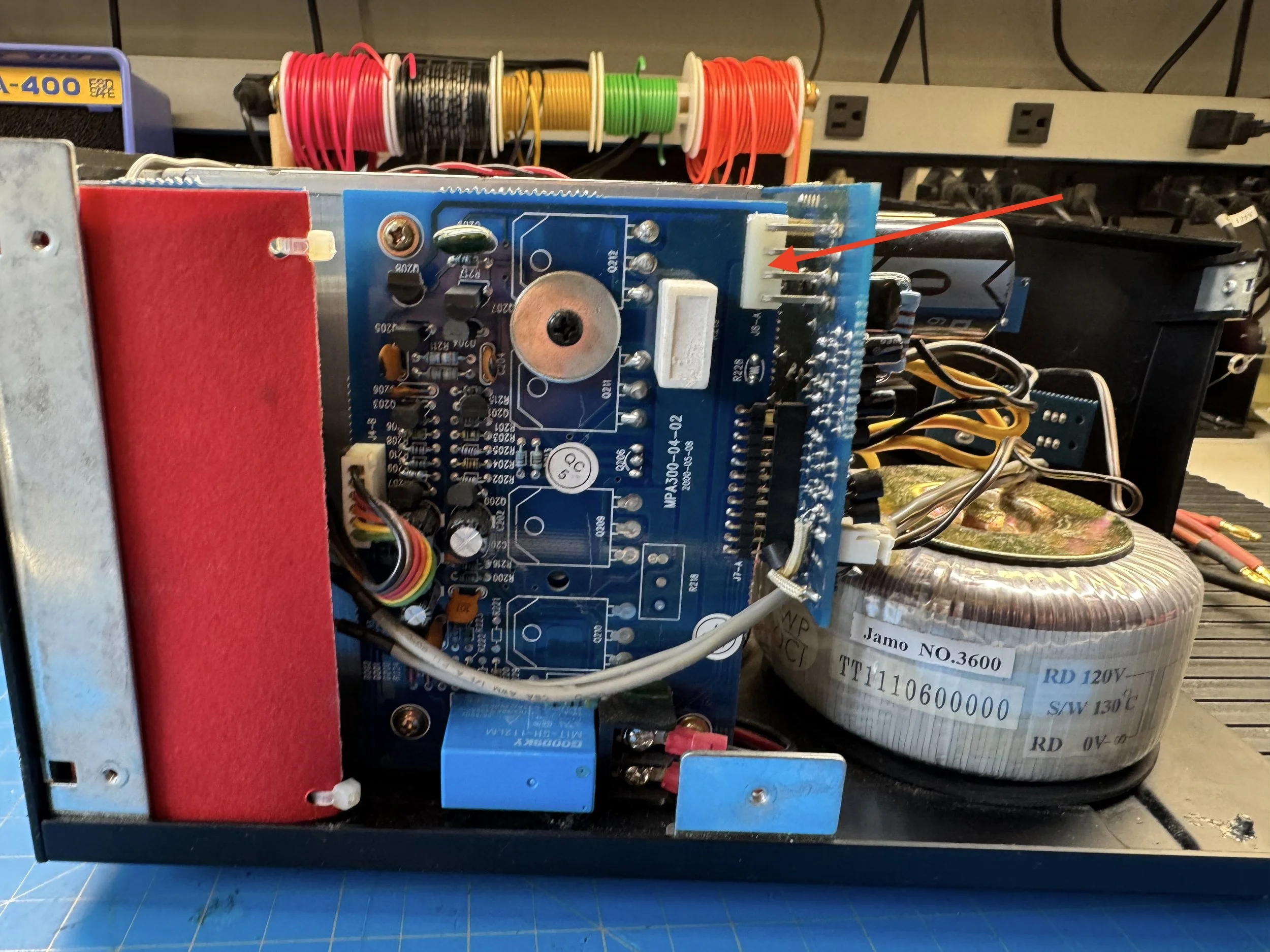
The edge connector at the other side. Yep, not much enjoyment to be had here!
Once you have sucked all the solder away, and it is a lot of work, you will remove 4 screws holding the board in place, and ease it out. You’ll also unplug a couple of cables, but the long grey ones can stay connected as they are plenty long enough to be able to access the board.
I also temporarily disconnected the volume control ground wire, and removed the upright brackets (one screw each) to move the front panel out of the way.
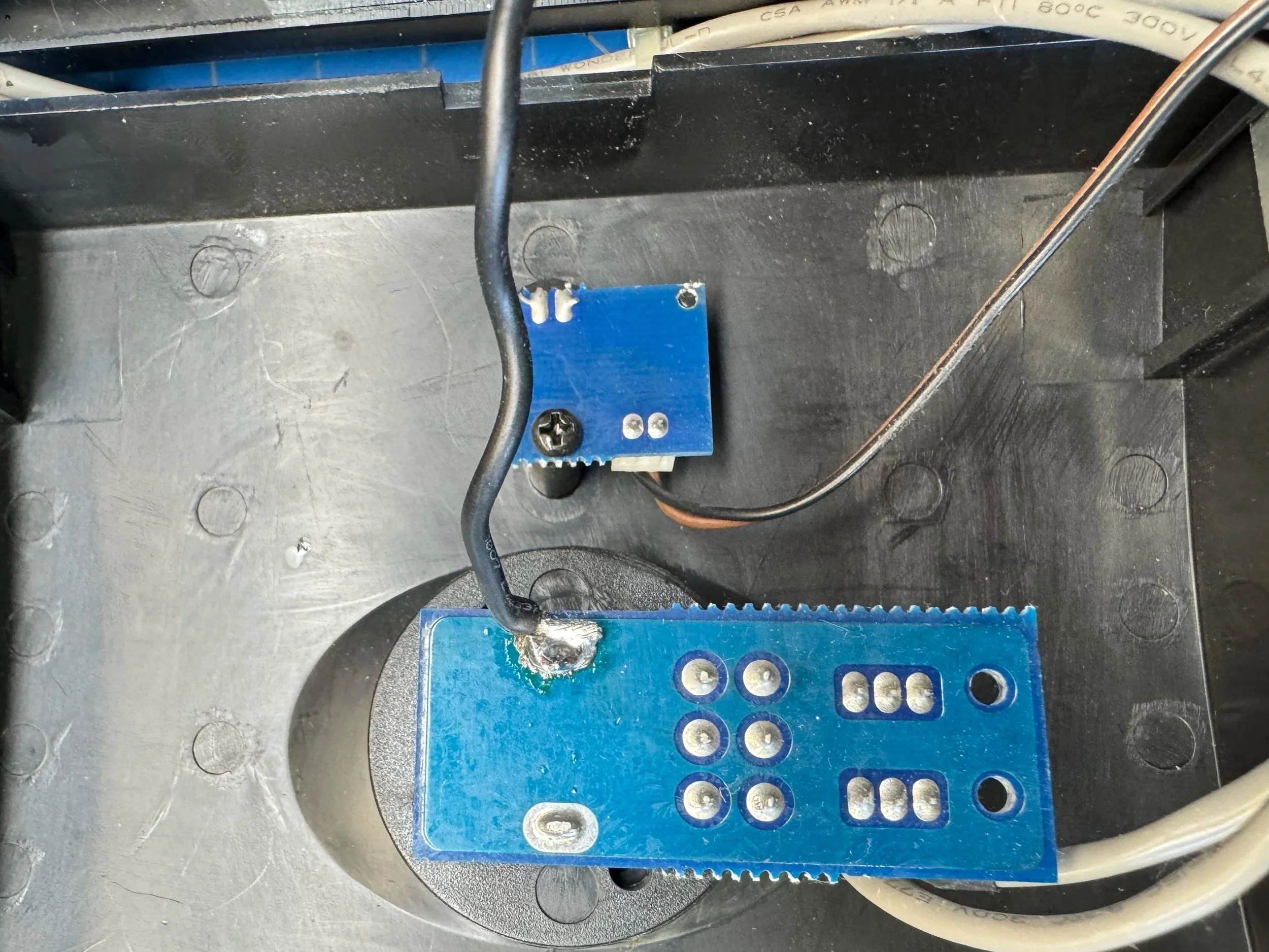
Ground connection in the back of the volume control. This is connected to the power supply board so makes it hard to access so just desolder it.
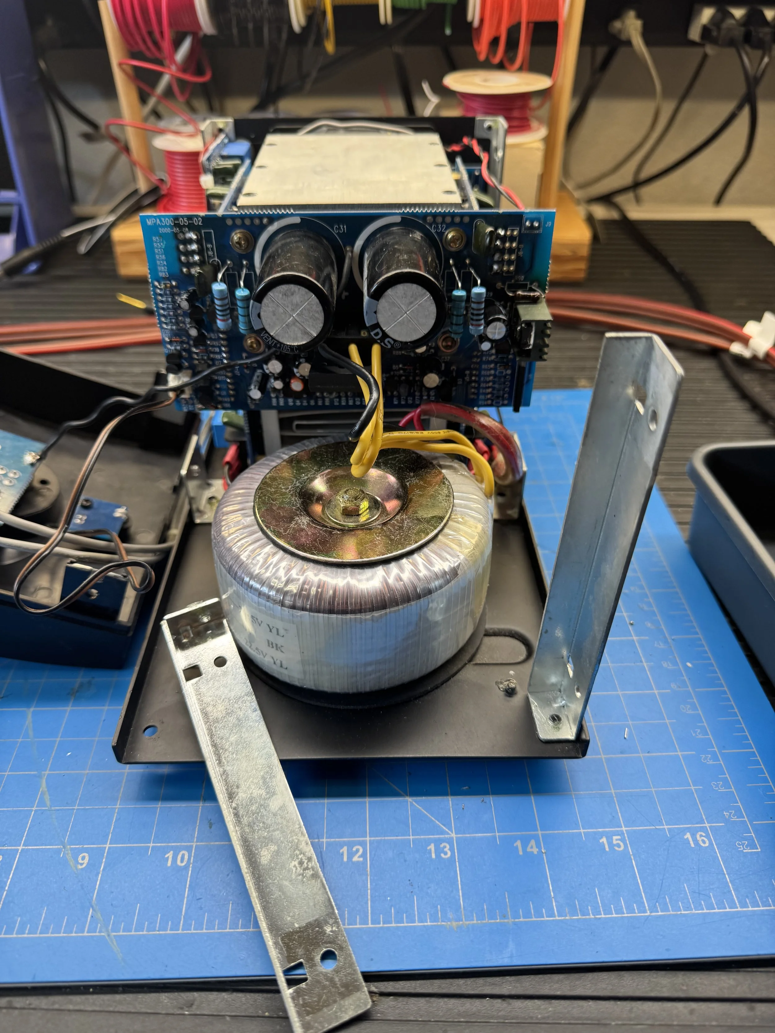
These uprights hold the front panel on, but they get in the way so take them out.
What was replaced?
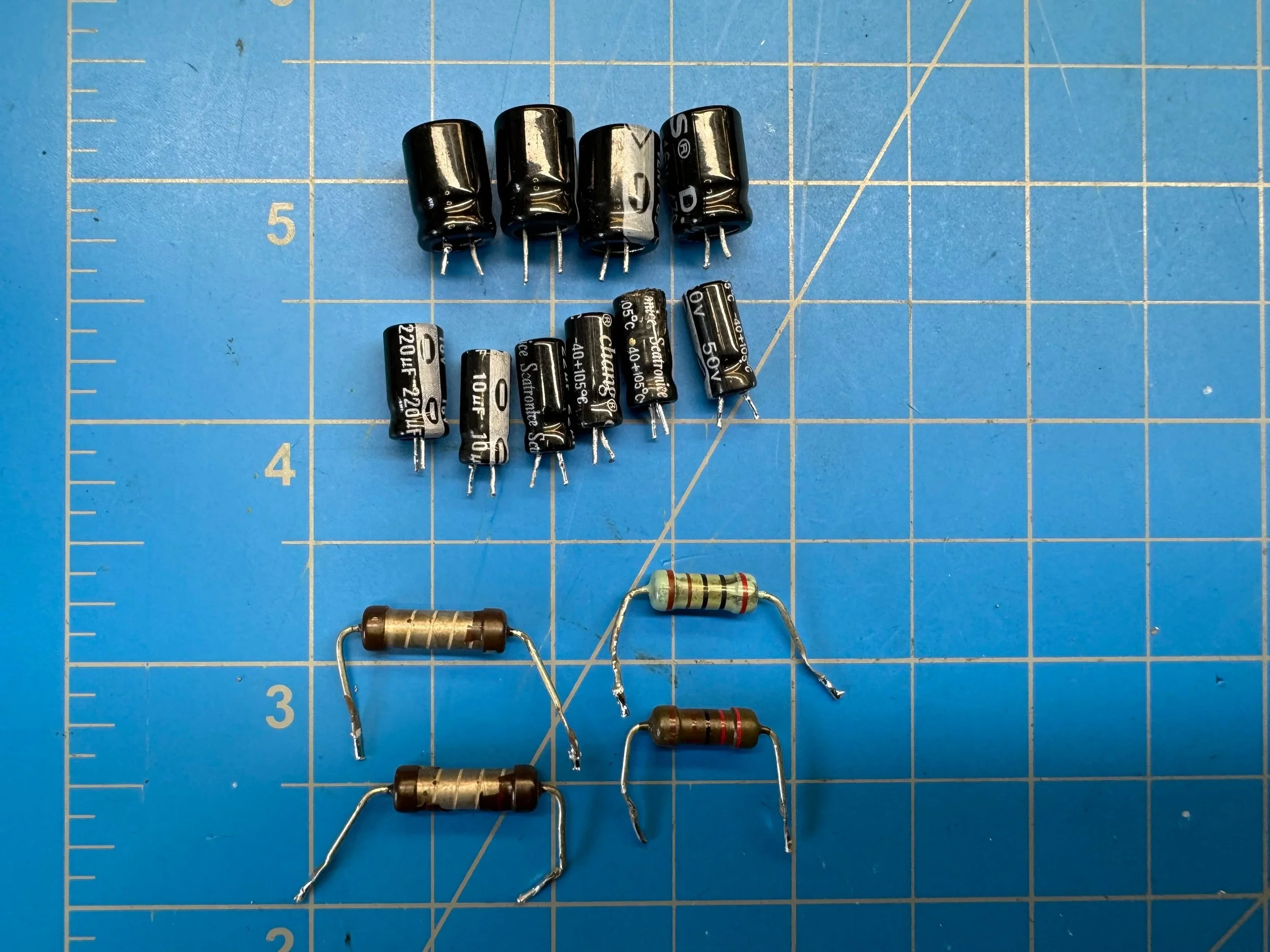
Ten capacitors and four resistors later.
The Process
I started by testing the infamous C39. C39 is often reported as electrically leaky in these amplifiers. In this unit, however, it had failed open and had effectively lost its capacitance. Dead as a dead thing. So I started testing other caps in circuit and was seeing a pattern. I replaced C39, and then one by one pulled each cap and tested them
Every single capacitor on the power supply board was either open circuit or badly drifted value or high ESR. I replaced every electrolytic capacitor with the exception of the large 6,800UF 50V caps. I did not have any in stock! But they tested good enough so I shrugged my shoulders and went on.
In the picture below you will see two zener diodes. They are also known to go bad, so test them! Just below the big cap you see them, two red parts with Z03 in-between them. Mine were fine.
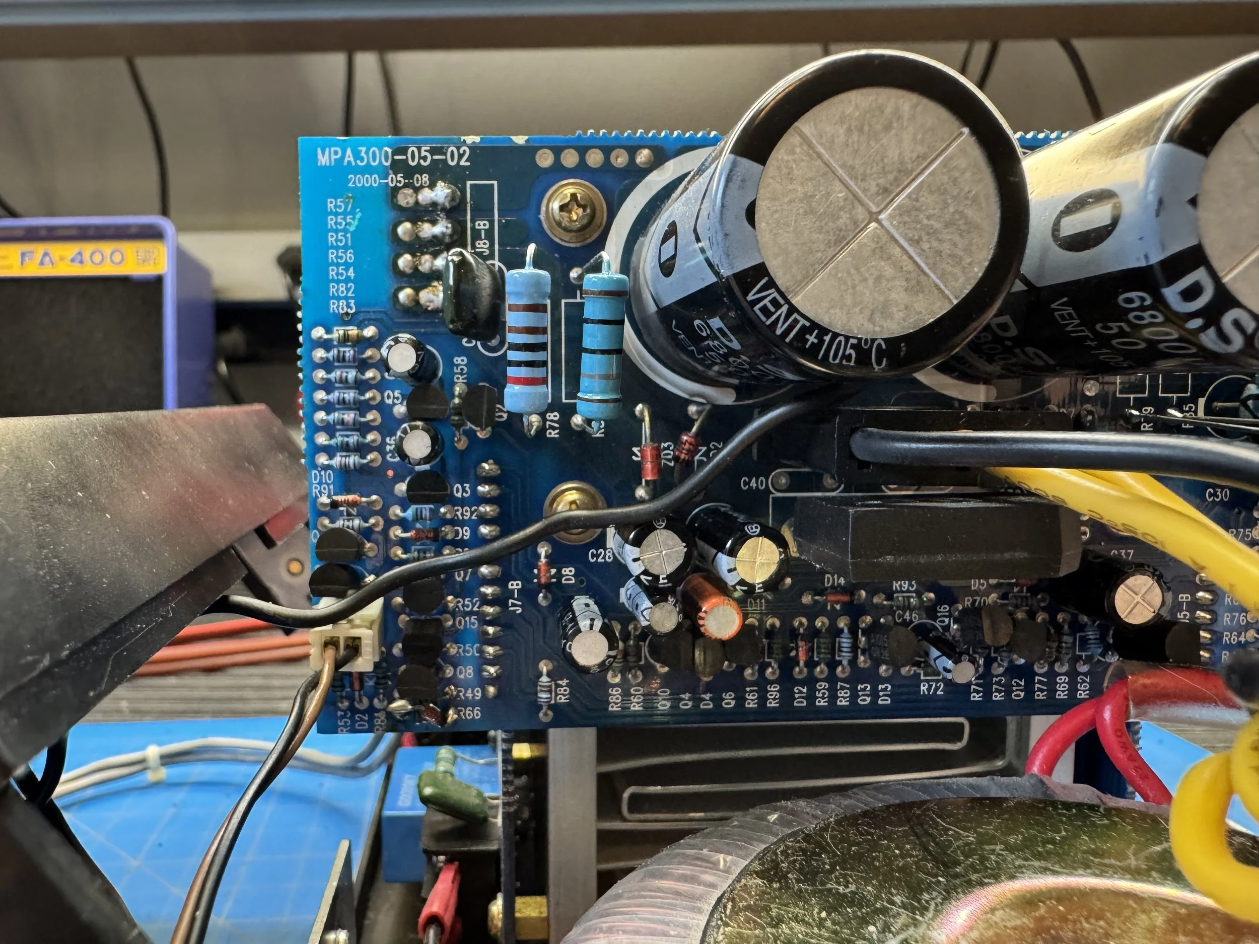
What about the rest of the amp?
A wiser man might have pulled the amp boards out as well and replaced the few capacitors on them. However, I decided it was worth testing it at this point, and pulling boards and thermal paste all over my fingers etc.
If you were going to town then you would pull both amp boards, and the input circuit pictured below.
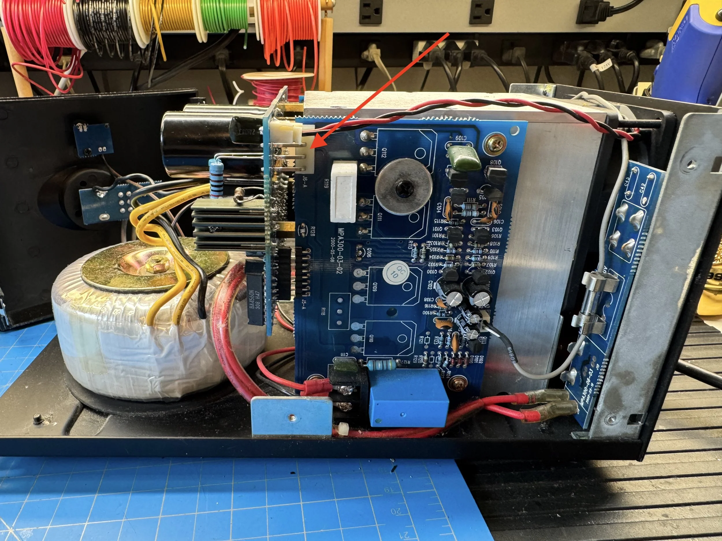
One of the amp boards. There are 4 small caps on each board, so yes, I was being lazy. The blue item is the speaker protection relay.
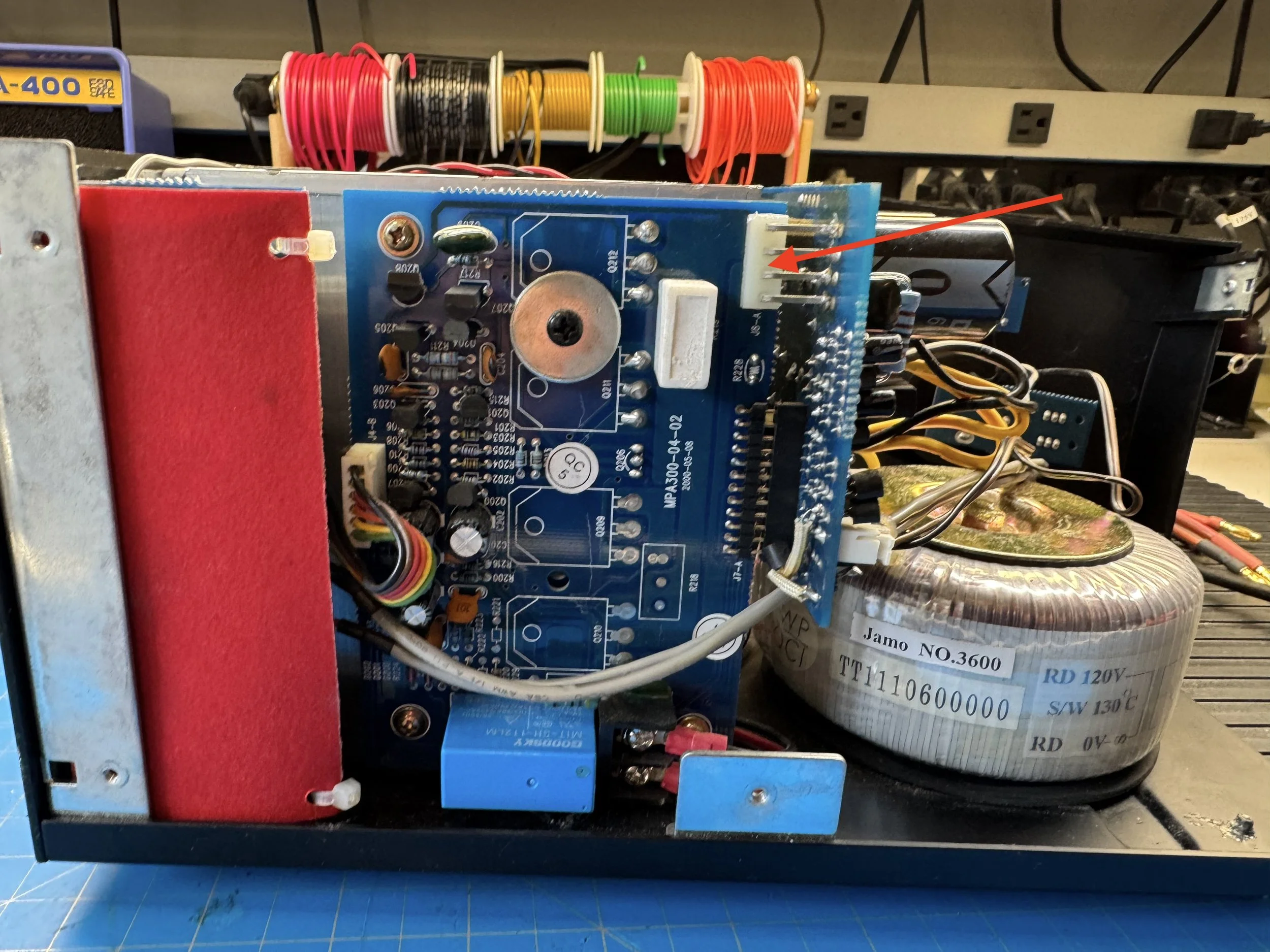
The matching amp on the other side. Note the red cover that hides the low pass filter (if using the amp to drive a sub-woofer), and the inputs. Note: you can connect a CD or Tape or anything else with just a line out.
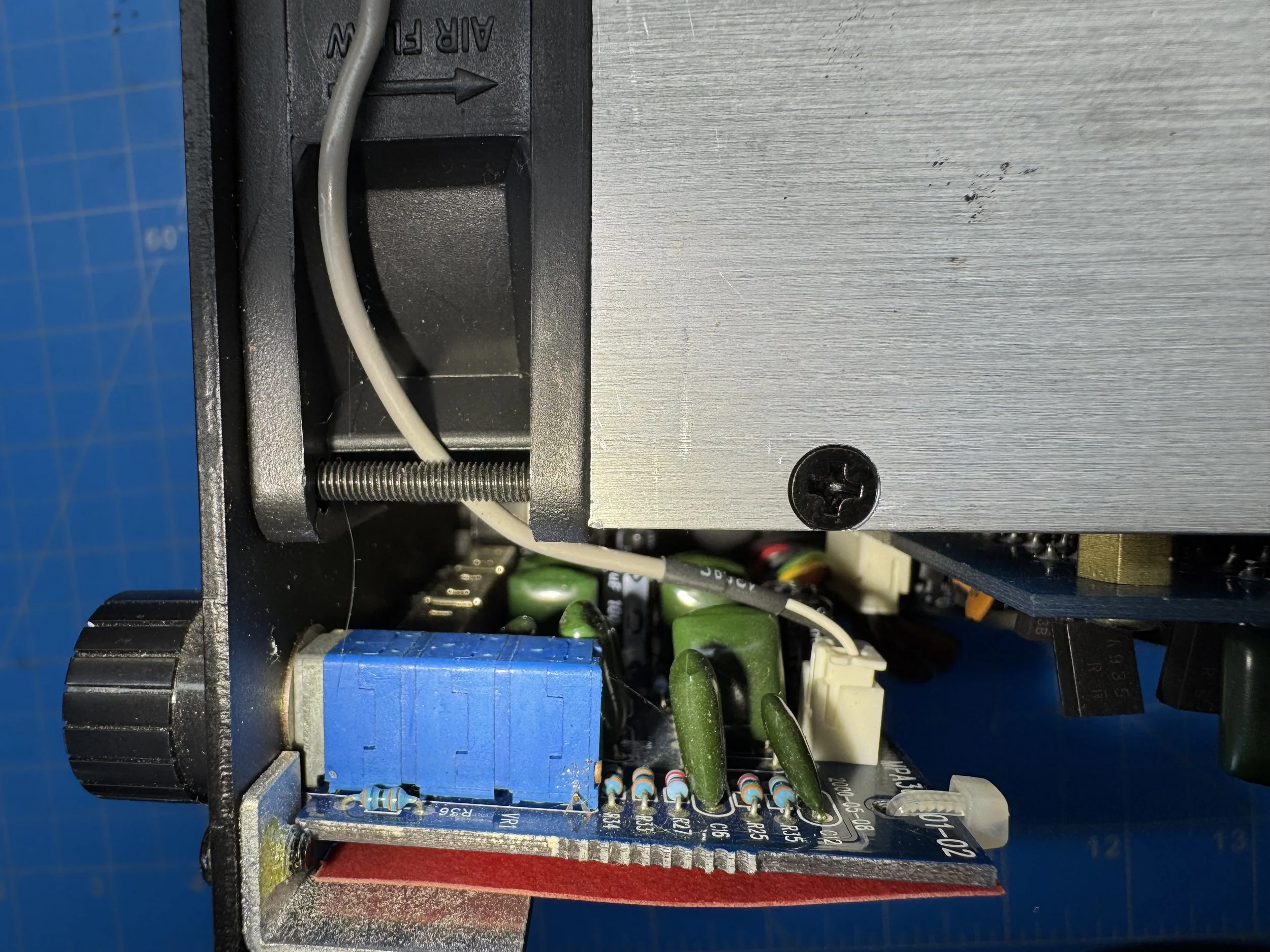
If you really want to go the whole hog, then there are a few caps here as well.
Did it work?
Yes it did. After refitting the power-supply board, the front LED illuminated and both speaker relays engaged after approximately three seconds. Testing with a source and loudspeakers confirmed normal operation on both channels. The repair required approximately three hours and around $10-$15 in components, although the labor involved would make this difficult to justify commercially given the amplifier’s modest resale value.
Had I had more issues the amp boards would have been next, but the heat this generates and the cheap capacitors used tend to lead to the main causes for failure to be the parts I replaced on the power supply board. The Zeners would have been replaced while it was apart but they tested fine so I shrugged again.
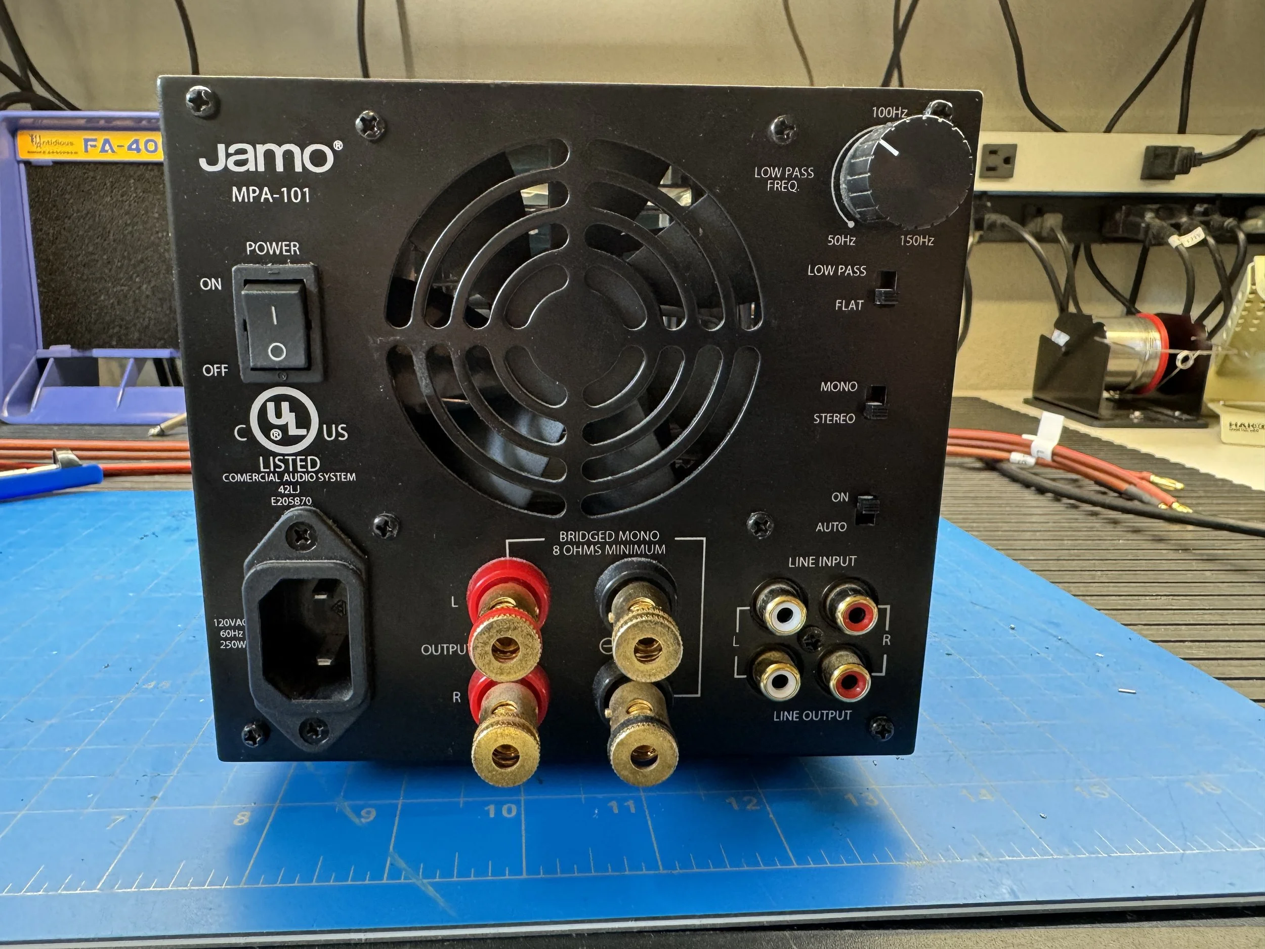
Auto on is a signal sensing so the amp remains in idle until it sees a signal on the line inputs. Line output allows you to daisy chain these amps for multiple speaker systems. Low pass kills all the high frequencies, so this is for driving a sub or big bass drivers.
And that’s about it. 3 hours work and maybe $10 worth of parts, but not economically viable for a customer to pay for repairs.
Should you buy one?
They sell on eBay and Marketplace for about 100 bucks, but unless they have been serviced I would avoid them, unless you’re handy with a soldering iron.
The usually safety warnings apply: High voltages and things that can be fatal. Only trained people should attempt repairs.
Pros
Reliable after recap
Good sound quality
Compact
Cheap
Cons
Runs hot
Poor-quality electrolytics
Difficult PSU board removal
Economically questionable repair
Circuit Diagram
I found a good high resolution PDF of the circuit diagram. Click the button below to download it. Always double check component values before assuming the diagram is correct.
Here is the parts lists for the parts I replaced:
Resistors
180Ω 2W | R79, R80
2KΩ 2W | R78, R85
Capacitors
470 µF / 16 V | C27, C28
220 µF / 25 V | C37, C44
220 µF / 16 V | C39
4.7 µF / 50 V | C35, C36
10 µF / 50 V | C34, C45