Quadraflex 575 Repair – Right Channel Low Volume at High Frequencies
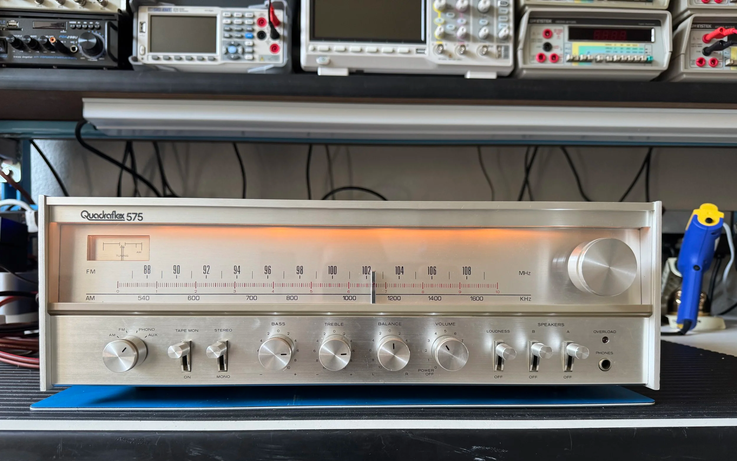
Restored, repaired, and once again displaying that unmistakable warm 1970s glow.
One of my customers asked me to take a look at this house brand receiver as he had owned it since he was a young man and it was the first real piece of stereo equipment he had ever owned. The Quadraflex 575 is a vintage AM/FM stereo receiver produced in Japan during the late 1970s as an affordable house brand for the Pacific Stereo retail chain.
Researching the receiver uncovered an interesting history. It was made by TCE which stands for Tandy Components Electronics (or Tandy Corporation Electronics), which is a name very familiar in Europe, but better known here as Radio Shack! Yep, they had their own vertically integrated manufacturing in Japan back in the day.
The Quadraflex 575 was manufactured and sold between 1976 and 1979 and was Pacific Stereo's budget-friendly, entry-level catalog offering alongside their larger, more powerful "Reference" series units.
An interesting footnote is that Richard "Dick" Schram, who later founded Parasound, spent part of his career with Tandy before establishing one of the best-known names in high-end audio.
Key Specifications
12.5 watts RMS per channel
AM/FM stereo tuner
Phono input
Auxiliary input
Tape monitor
External antenna connections
Outputs: Speaker A and B and headphones
Like many receivers of this era, it has no speaker protection relay, so the speakers produce the familiar power-on thump/buzz before settling down.
The only chip I found is in the FM multiplexer and tuner, and that was a Sanyo part, another Japanese firm long since gone. FYI Sanyo means “three oceans”.
What was the fault?
The customer showed me that the right channel was quieter than the left and the balance control had to be set around the "4" position to centre the stereo image.
Time to remove the covers. The receiver has a wrap-around wooden case secured underneath.
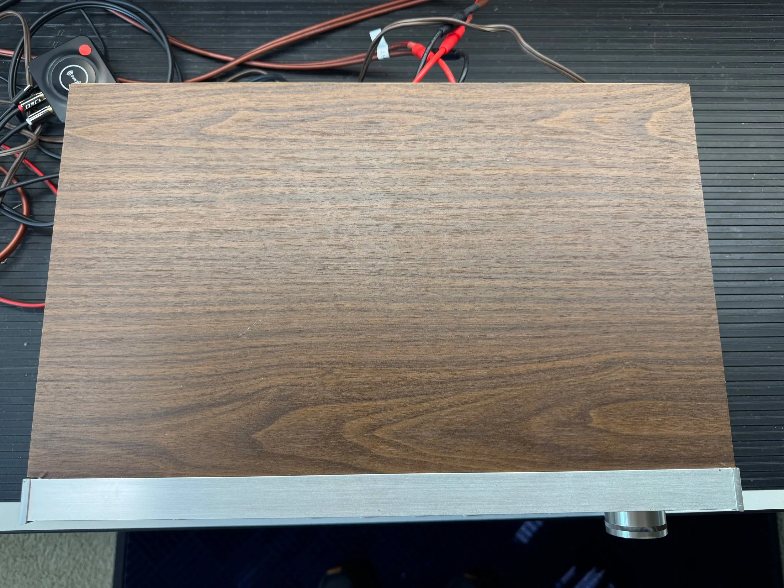
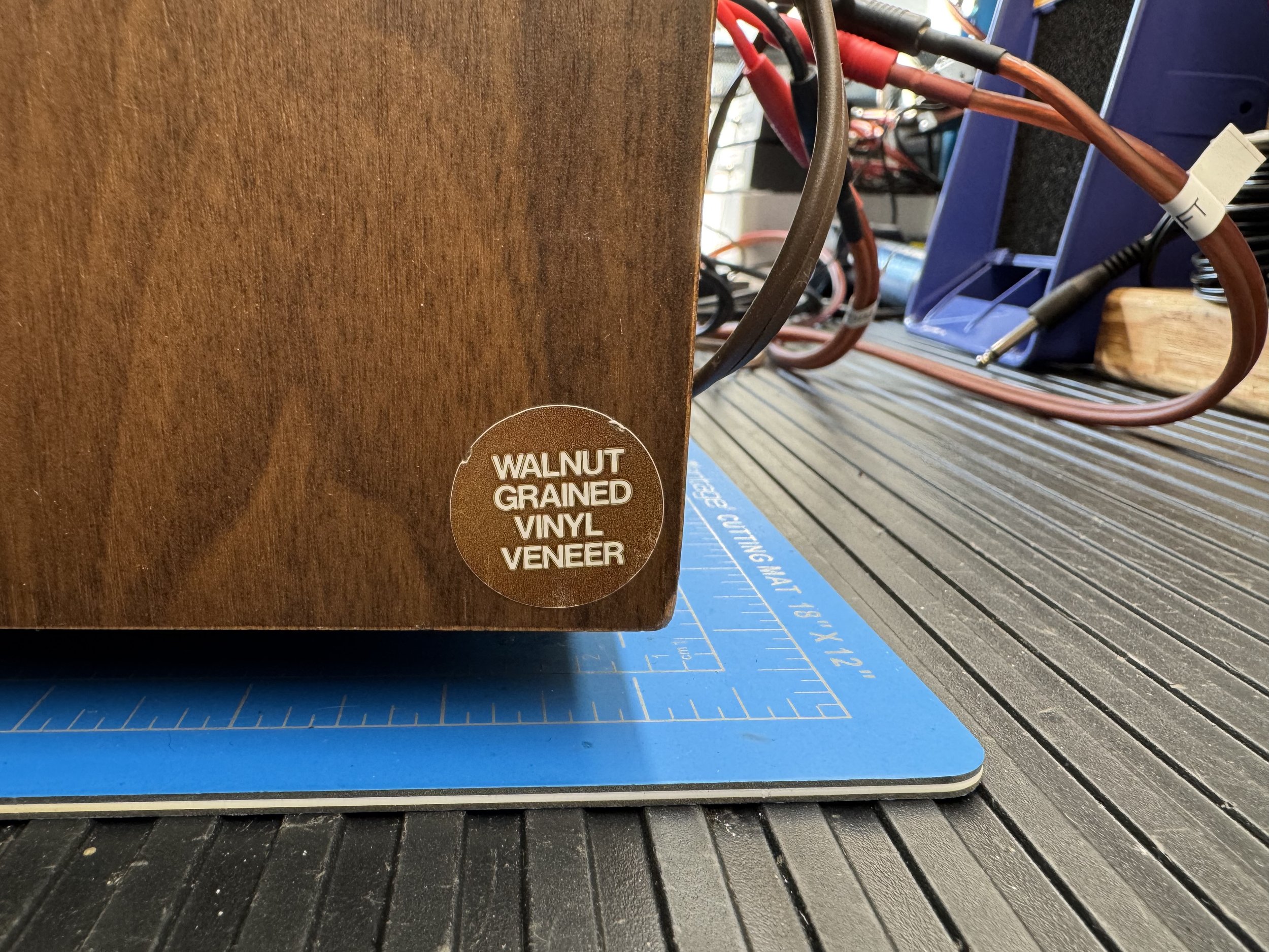
Is this wood or not? The inside is wood but it seems the grain is a vinyl veneer.
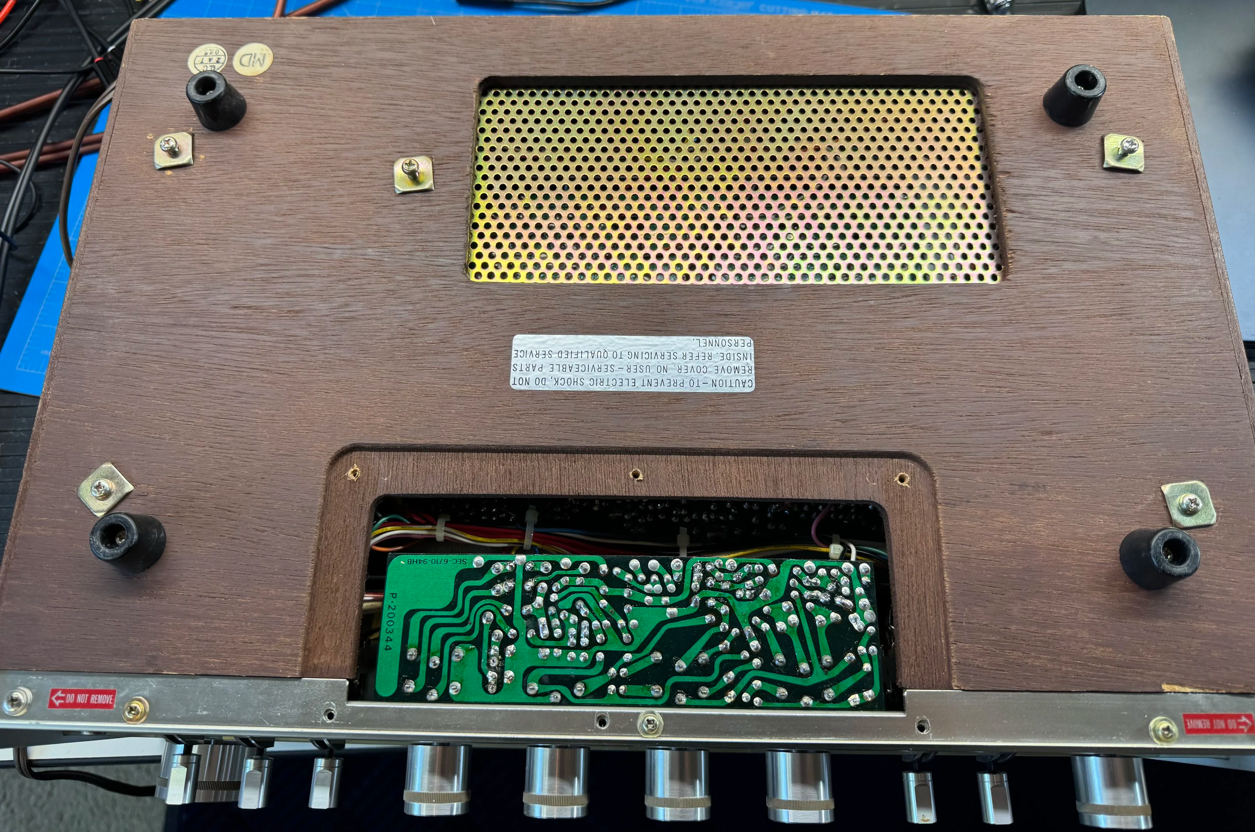
There is a metal panel, shown removed, which reveals the preamp board and used mainly for screening.
The fault was on this preamp board, which we will see shortly, but this access does not help servicing.
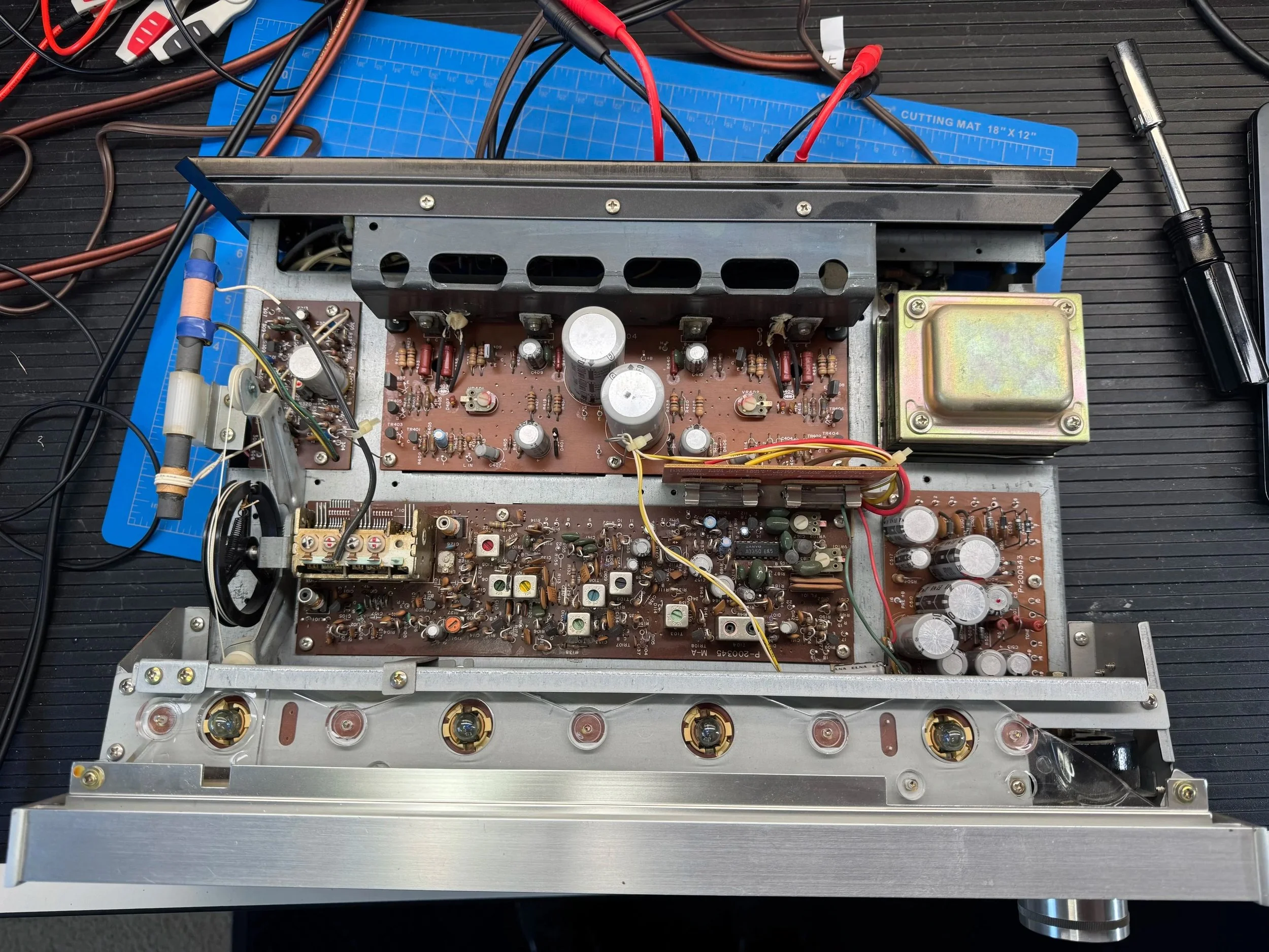
Top down view with the cover removed. Power amp board is to the rear. Power supply front right and FM tuner along the front. AM tuner top left. Note the dial cord layout. That becomes very important soon enough.
Testing
I first confirmed the fault by listening, then cleaned the potentiometers to eliminate oxidation as a possible cause. Unfortunately, the imbalance remained.
The next test was to see what the output was on each channel. I connected an audio source directly to the power amp inputs internally. Very easy to find on the underside. Red was the right channel and white the left.
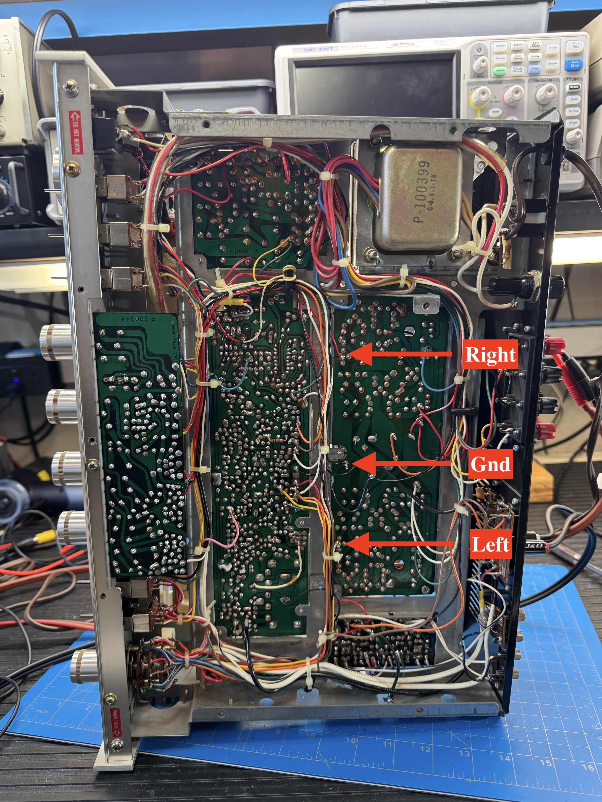
I connected a preamp to these connections and used a signal generator to send various levels to the amp. The channels were both equally balanced which eliminated the power amp as the issue.
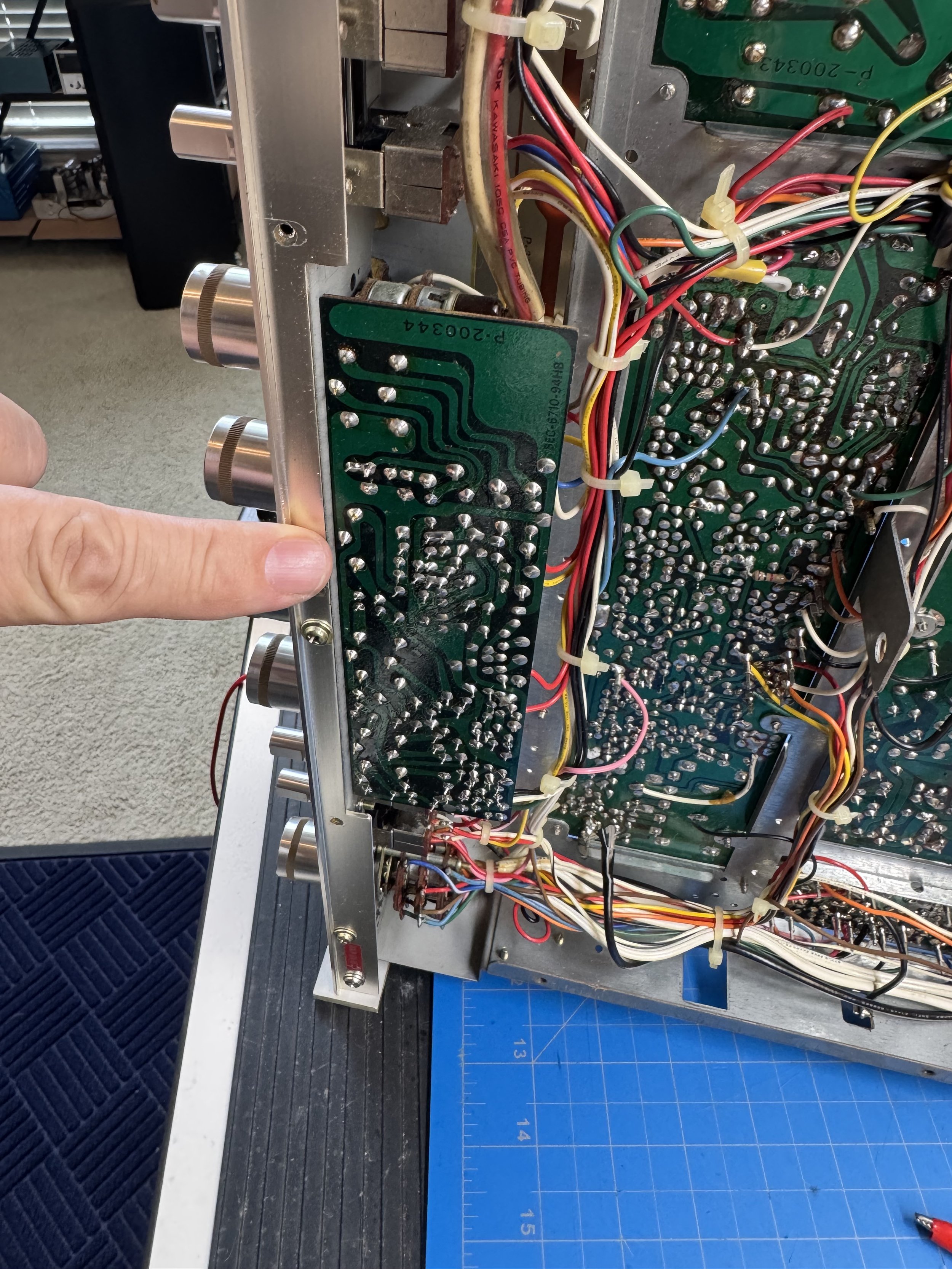
This is the preamp board we saw earlier. This is where we will find the fault.
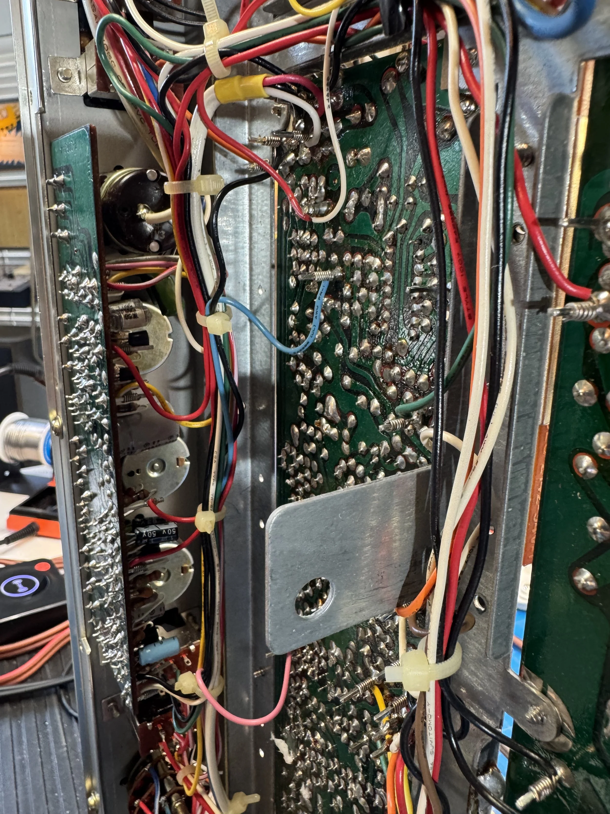
A closer view of the preamp board. Let’s get the front panel off to get access to the preamp. And this is where the fun will begin!
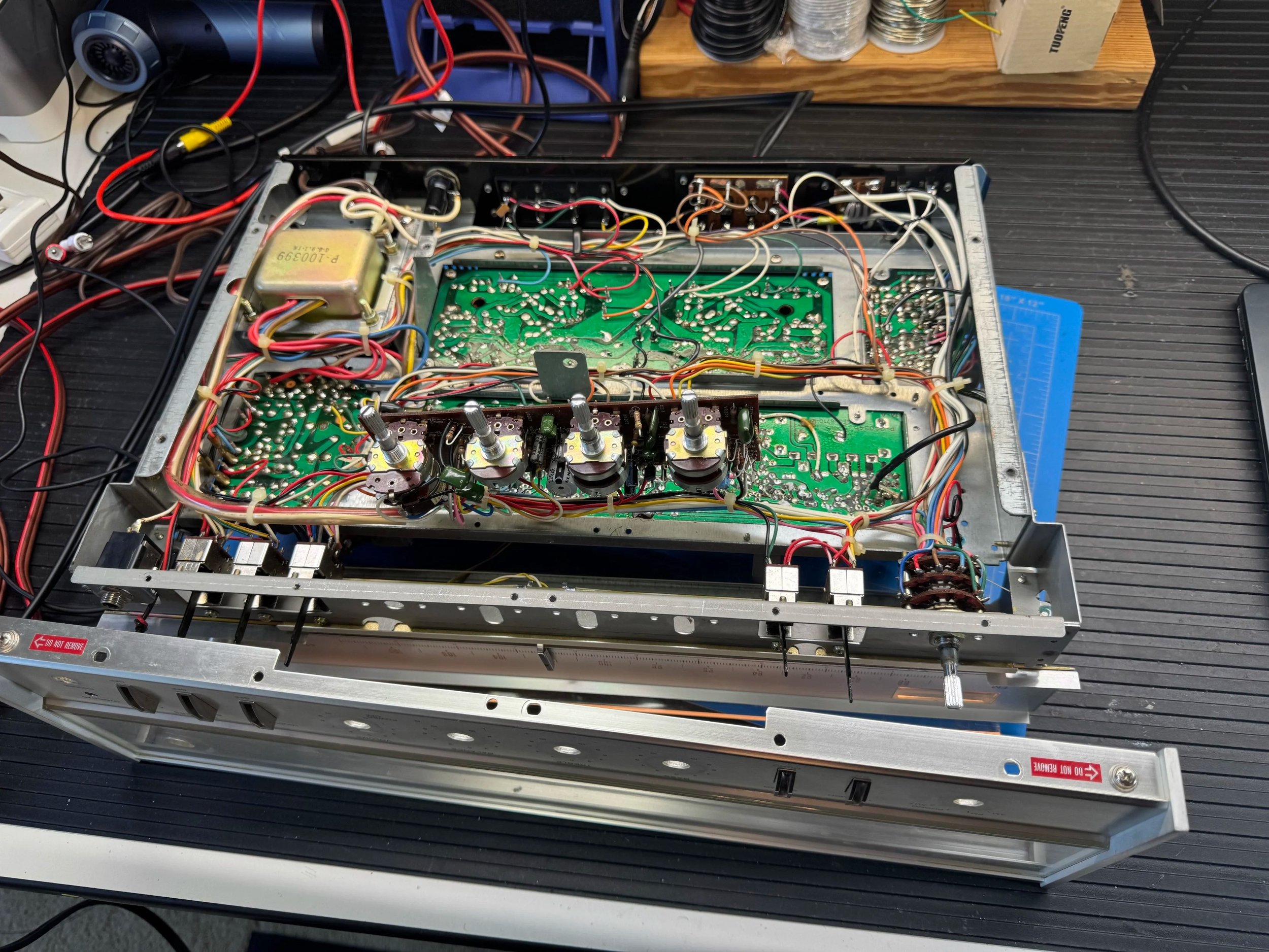
The front panel comes off after removing all the push on knobs and small silver caps for each toggle level/switch. You can see the panel detached and the preamp released from the front panel to be worked on. BUT, the tuning knob simply would not pull off. At first I thought it had seized on the shaft. It turned out that a someone had actually glued it in place.
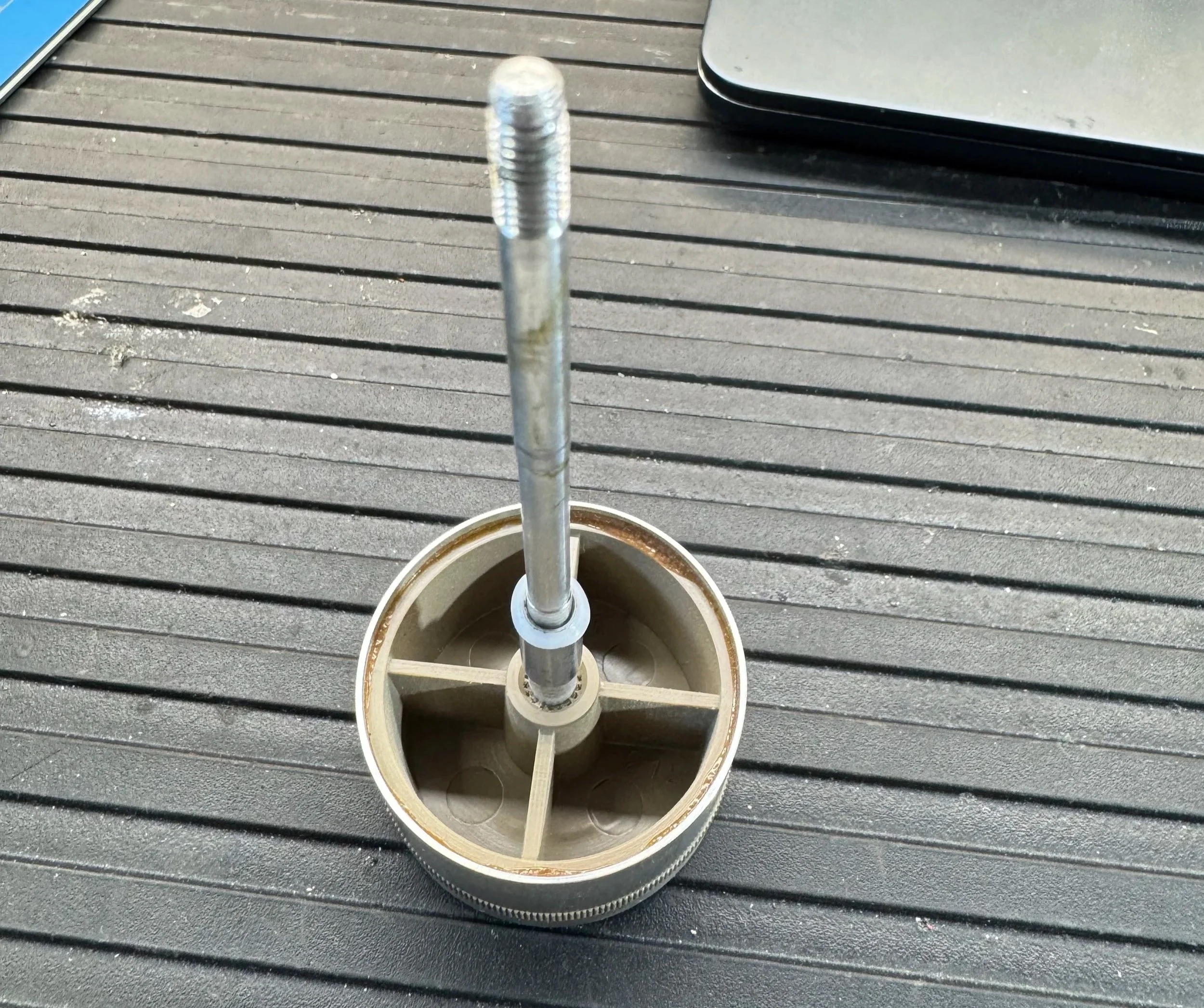
The tuning knob removed. You can’t see it easily, but the center is glued to the shaft. I ended up having to pull the enter shaft out.
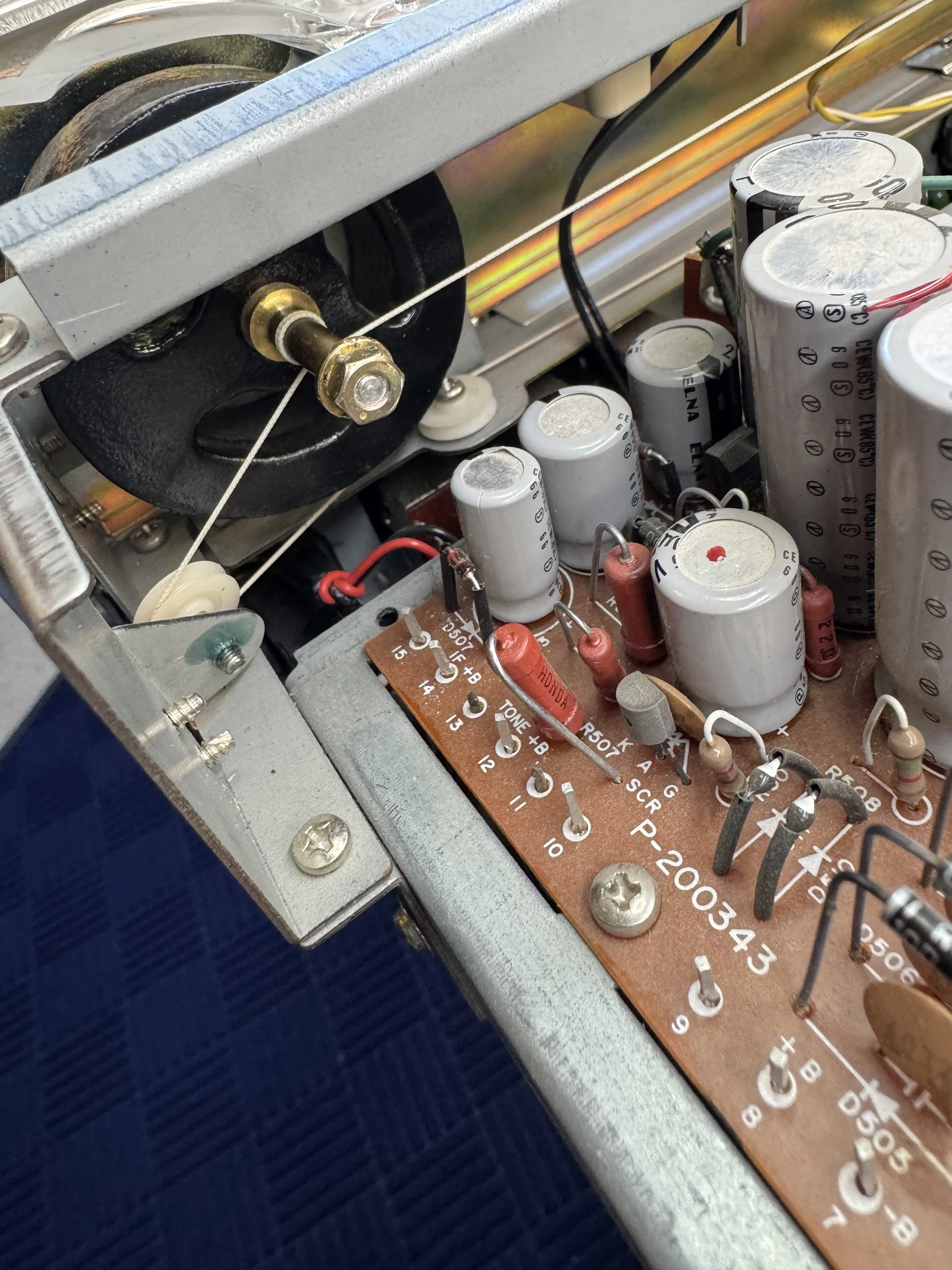
The tuning dial is connected to a shaft which adjusts using that small nut. To release it the nut must be removed. It was very tight! Once removed the shaft unscrews and pulls out. Warning: Doing so allows the tuning counterweight to swing free and if you are not careful that dial cord will come adrift and then your day will descend into guessing how the cord is threaded. Note: there are no service manuals for this so take a lot of photos!
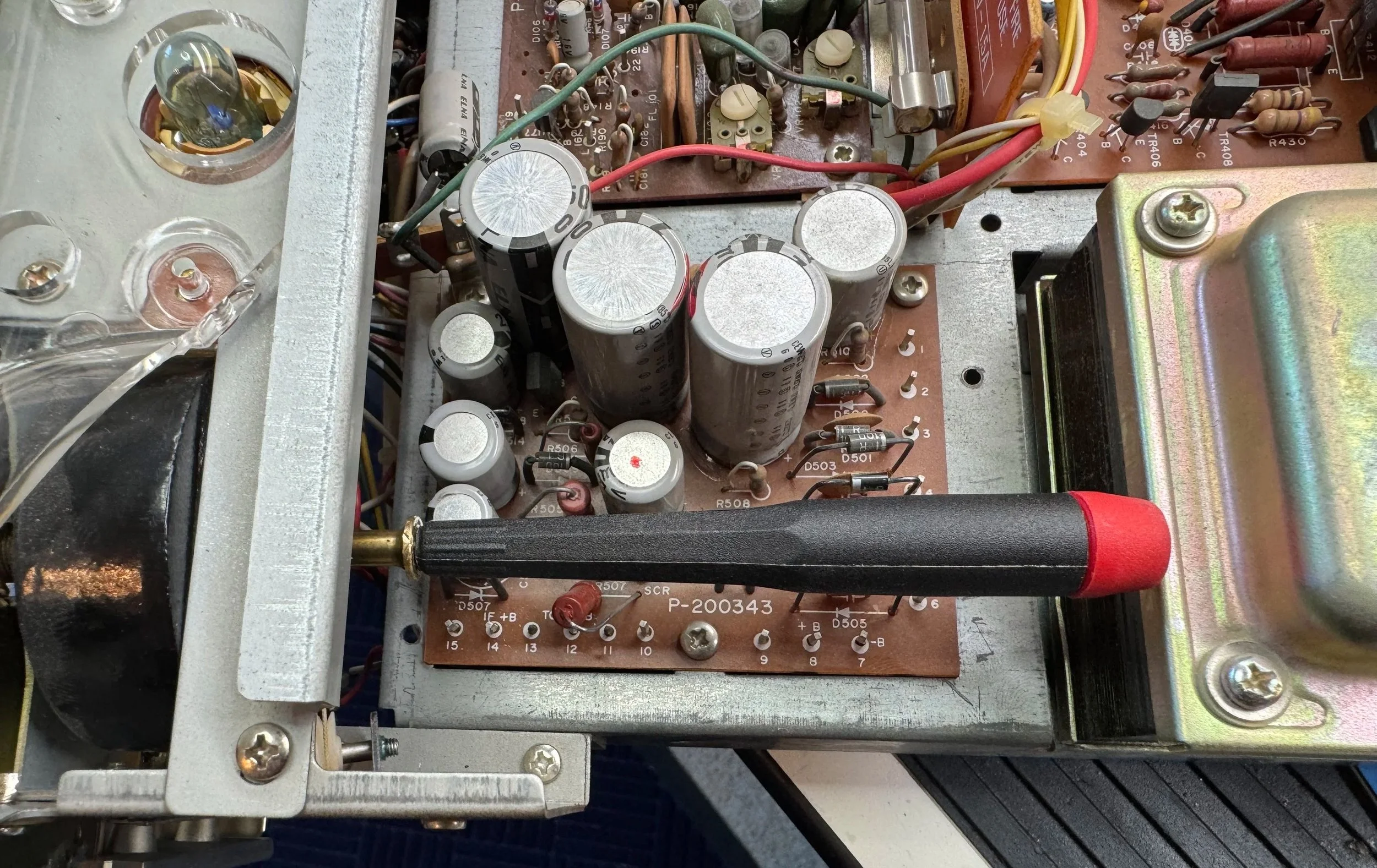
Tip: What I did was slide a screwdriver in as I withdrew the shaft so that it held everything in place. This proved to be effective and prevented that weight from moving too much and allowing the dial cord to detach. Phew!
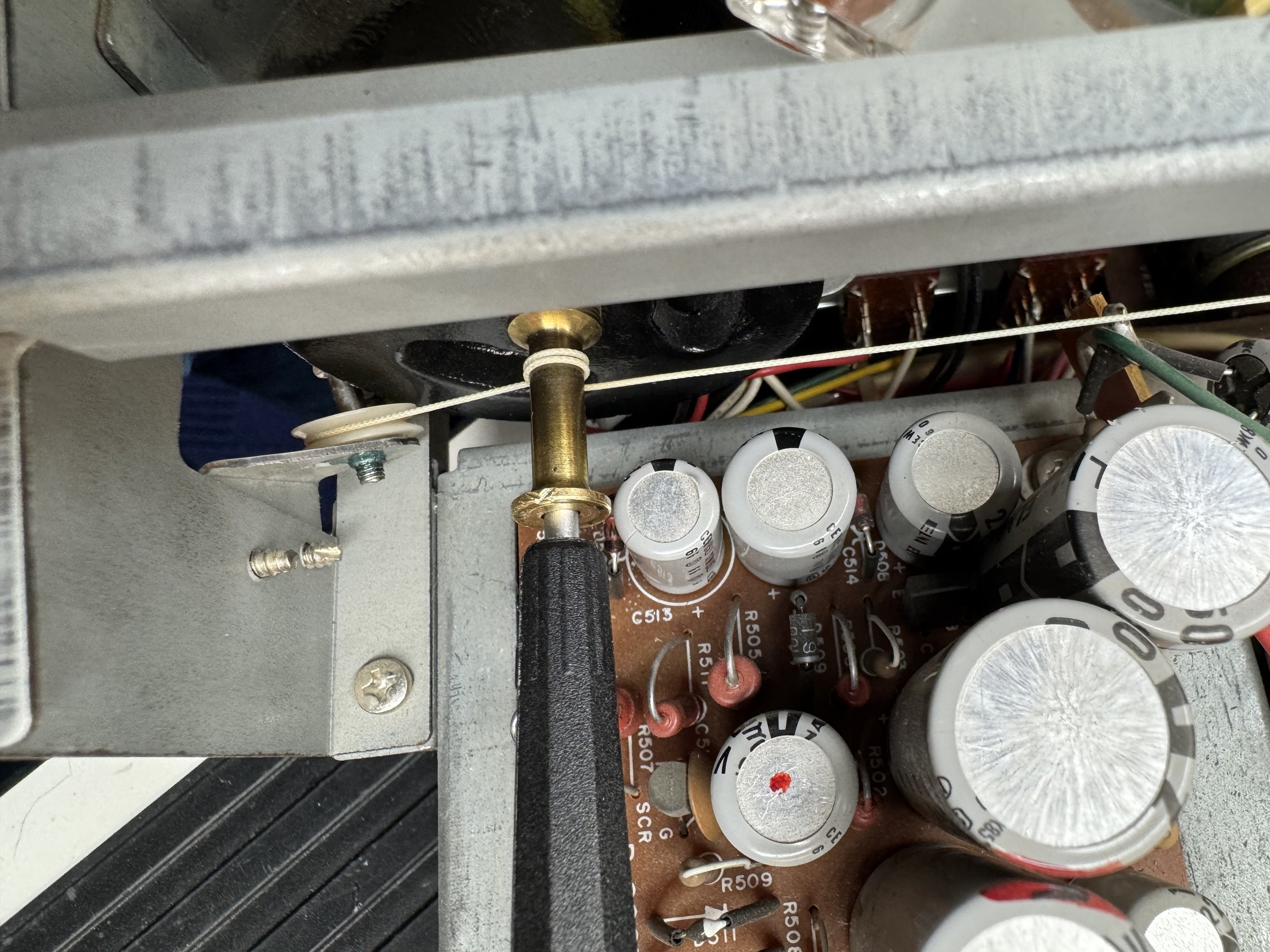
Here you can see the dial cord on the back of the counterweight. The tuning knob shaft slides through that brass collet where the screwdriver is currently holding things in place. Also watch the dial cord does not come off that small plastic wheel.
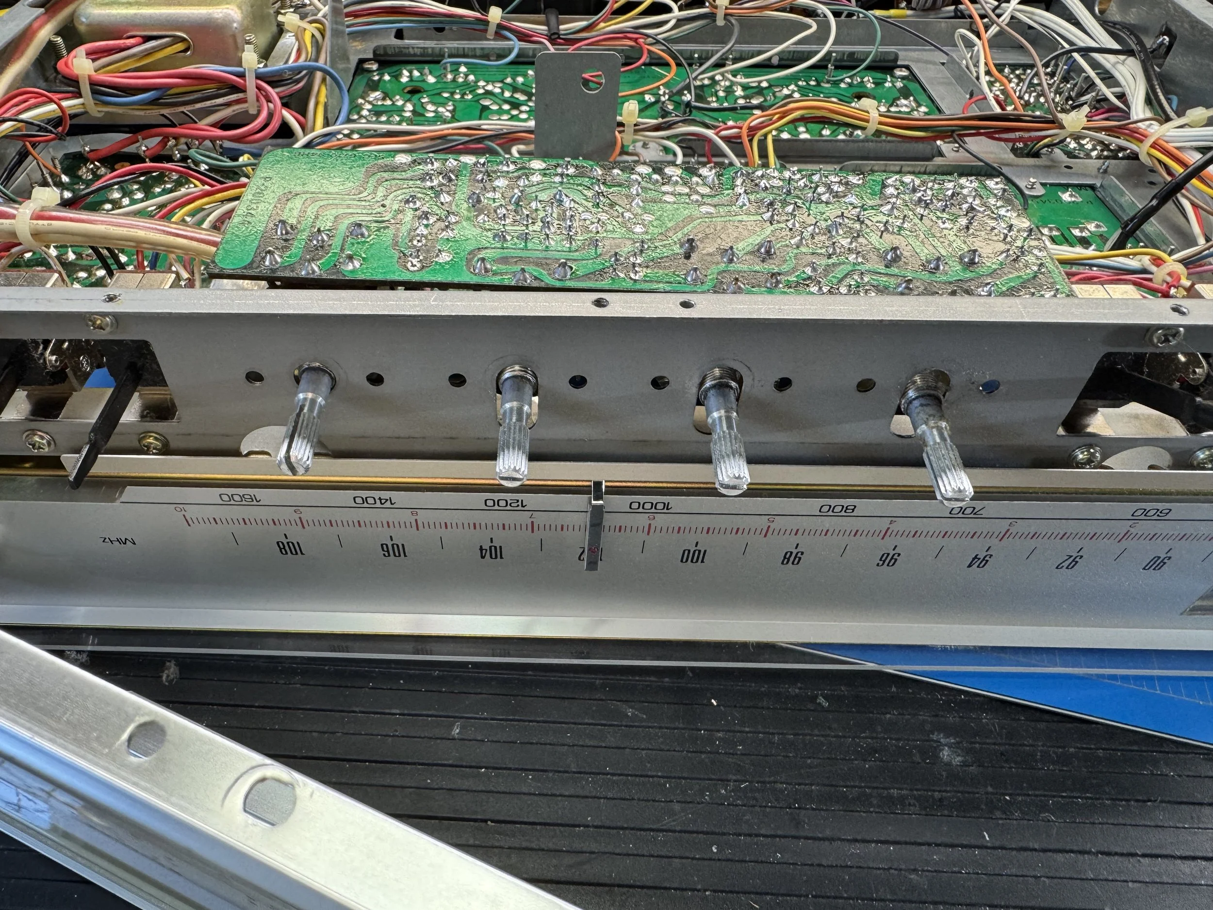
Here you can see the front panel removed and the preamp partially released.
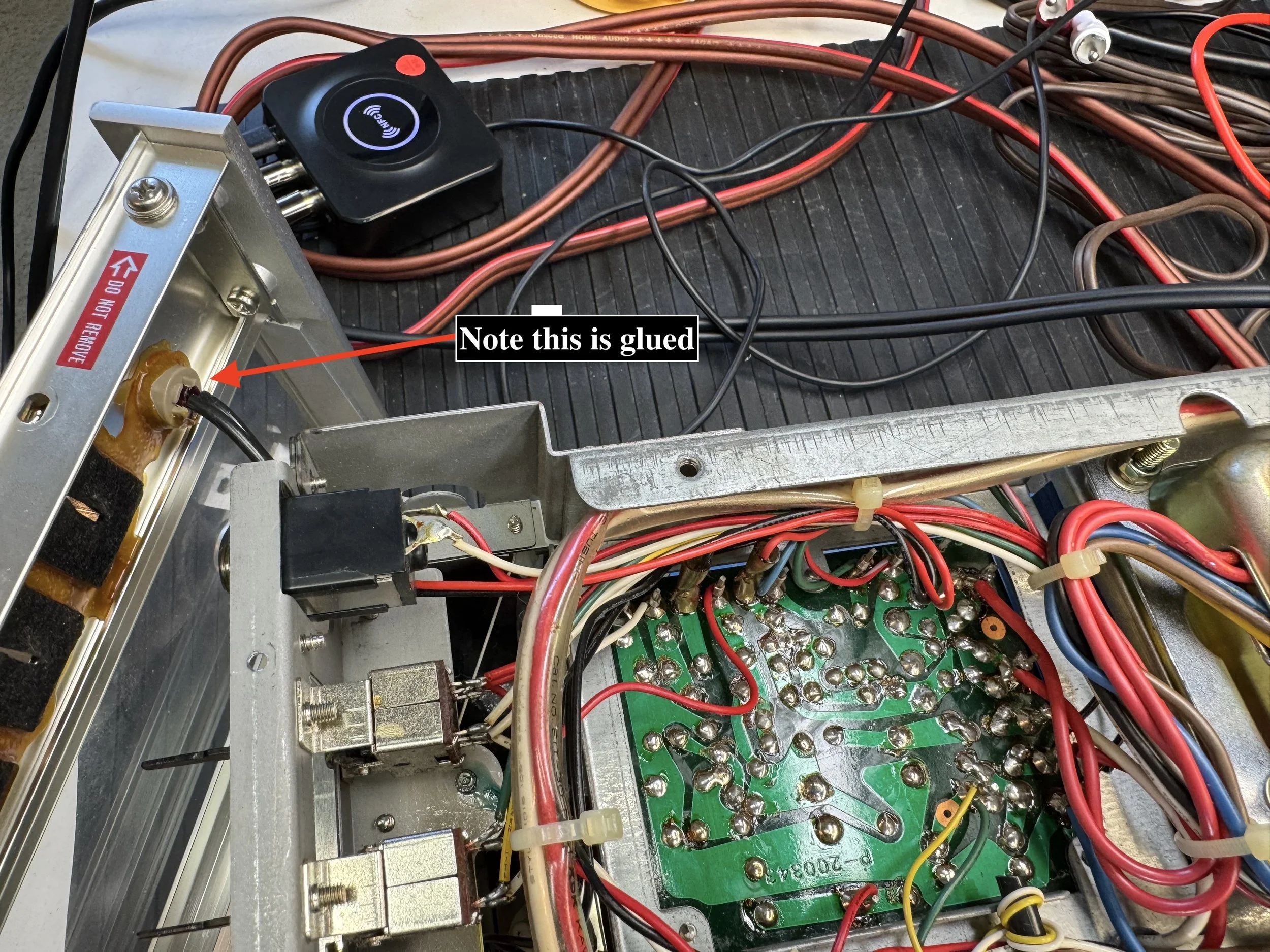
And this is why the front panel was never far away from the unit. There is an overload indicator LED glued into the front panel but there is enough room to move the panel our of the way to get the preamp board out.
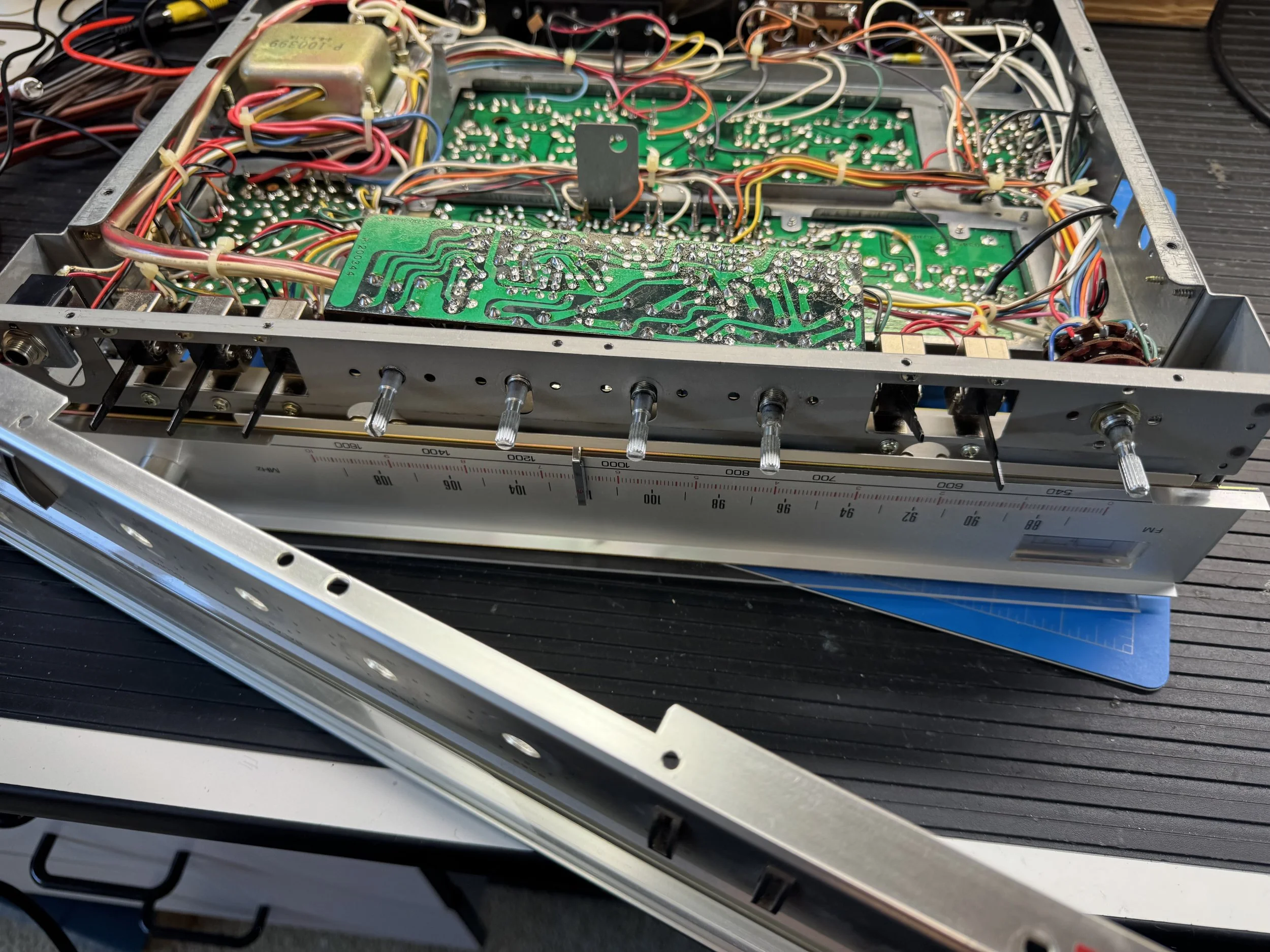
Here you can see the access gained to get that preamp board released.
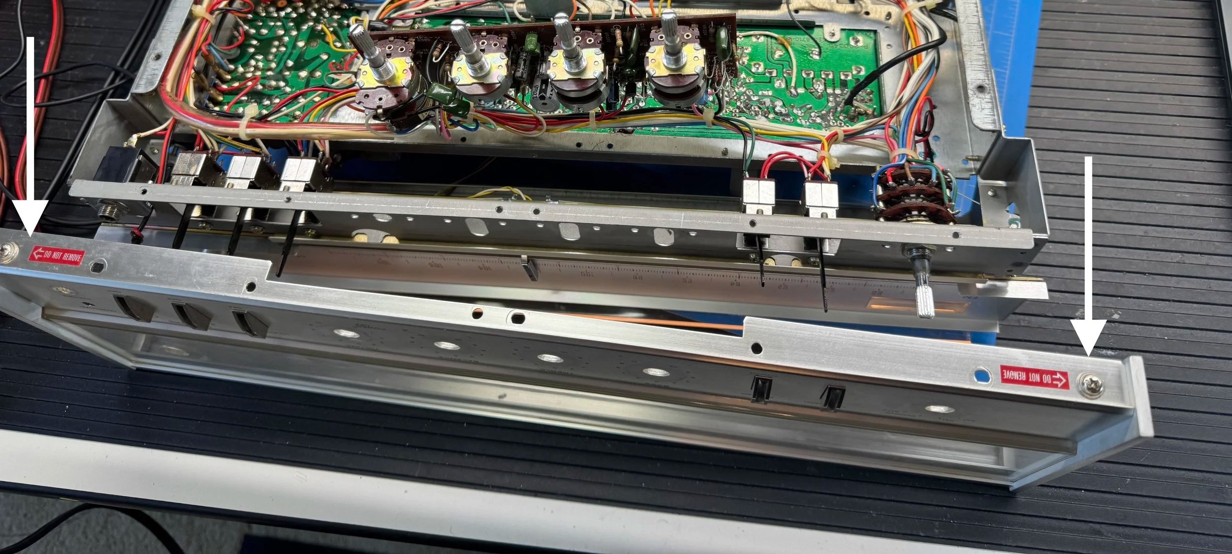
Note: Be careful not to remove the screws shown by the white arrows and red warning labels or you’ll end up with parts on your bench that you didn't want, and you'll create considerably more work than you intended.
What Was Wrong?
The next step was to test the preamp output to confirm it was the issue. Using the same connections on the power amp board I connected a volt meter on AC MV scale.
I used a signal generator connected to the aux inputs in mono using a two into one RCA cable. At 100hz there was no discernible difference. At 1khz a small difference but nothing significant. At 10khz the difference was huge. 60mv on the left channel and 30mv on the right channel with the volume control set low between 1 and 2 on the scale. You are looking at voltage differences, not output power. Turning the treble gain control up only made the imbalance worse.
This would typically indicate a failed ceramic capacitor potentially in the tone control circuit. But ceramic capacitors almost never fail. I set to testing a few using an in-circuit tester and could not fault any of them, but as I tested around the board I got inconsistent readings on one ceramic capacitor. It was one of a pair on the dual gang volume control.
I decided to lift a leg on each of them to get a good reading. Once I started to test them I spotted one that was actually moving where it attached to the volume control. And there it was. A poor quality solder joint causing that high frequency capacitor to disconnect. So at higher frequencies the capacitor was effectively disconnected, reducing the gain of the right channel.
I soldered that lug, re-soldered the capacitor legs back to the board and turned it on to repeat my tests. Success. The right and left channels now measured identically across the frequency range.
Lesson learned: Don't assume every high-frequency imbalance is caused by a failed capacitor. Poor solder joints can produce exactly the same symptoms and should always be ruled out before replacing components.
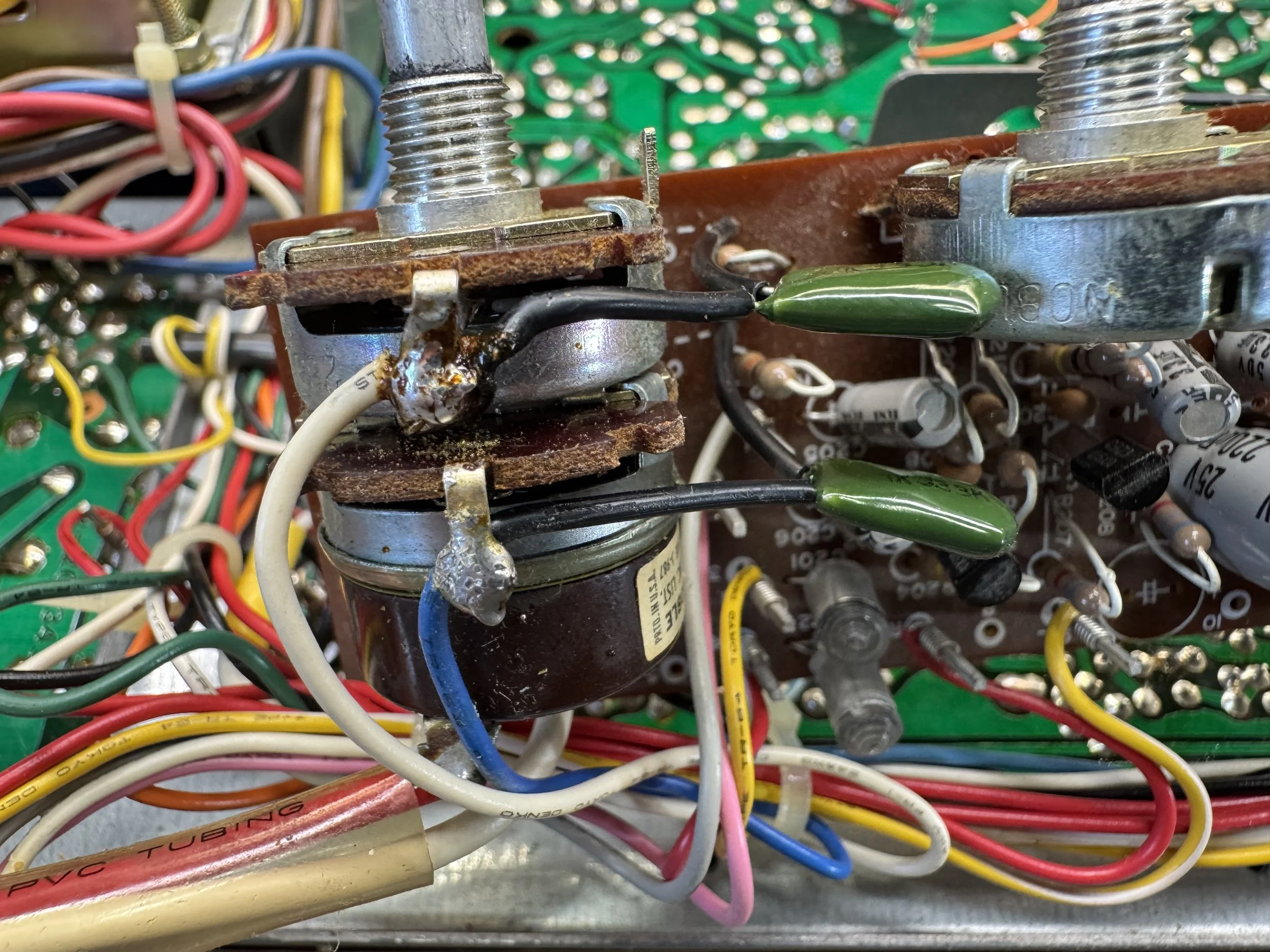
The top lug with the white lead was the issue. Note the quality of the ceramic capacitors used. That’s the Japanese for you.
It's impossible to judge the sound quality from an iPhone video, but I was genuinely surprised by how good this modest 12.5-watt receiver sounds when paired with efficient loudspeakers. Like many Japanese receivers from the late 1970s, it delivers a warm, engaging sound that is far more impressive than its modest specifications suggest.
This Quadraflex 575 is now ready to continue doing exactly what it has done for nearly fifty years, bringing music back to life for its owner. There's something immensely satisfying about repairing equipment that still has sentimental value to the people who own it.